↑ TrillSat
Page Created: 4/6/2018 Last Modified: 4/13/2026 Last Generated: 7/27/2026
IoT meets AX.25 aboard an Arboreal Space Elevator
Texting Without Cell Towers, Power Grid, or the Internet
A Tethered, Radio-Interfaced, Laterally-Leveled, Spiral-Axis Tracker
by Lee Djavaherian
(This article contains references to Amateur Radio technologies that may require licenses in your country, but the robotic platform can be adapted to use license-free consumer radio technologies with varying results. Please note that I am not an engineer and have created this system for my own use and self-education only, with the hope that providing information about the project will be useful to others in some way. It might not be suitable for you, and I am not responsible for the correctness of the information and do not warrant it in any way.)
- Introduction
- Design
- The Electromechanical Machine
- Exploded Diagram
- PETG 3D-Printed Modules
- TRILLSAT-1: My First Prototype
- 18 Unique 3D-Printed Parts
- Three Circuit Boards
- The Full Schematic
- MOSFET Insanity
- Qi Wireless Docking at the Space Port
- Four CPUs
- Ten Temperature Sensors
- Solar Power Subsystem
- Hanging Zepp Antenna
- Six Radio Links
- Battery Redundancy, Capacity, and Monitoring
- Trees, HAAT and the Capstan Hoist
- UV, Wind, Rain, Hail, Ice, Snow
- Light, Sound, and Vibration
- Emergency Landing
- Modes
- The Software
- Algorithms
- Five Programming Languages
- Ten Protocols
- Maxing out the ATtinys
- Minimizing Power Usage
- The Delta-v Motor Drive System
- The Powerful PBBS
- The Smartphone Meets Packet Radio
- Auto Network Failover
- Interrupting an AX.25 Session
- Constructing an APRS Packet
- Wrestling with the \r Delimiter
- Concurrent Programming Nightmare
- Building a Multi-User System
- SOCK_SEQPACKET?
- Source Code
- Construction Techniques
- Tools and Materials
- Operation
- Program Description
- config.txt
- cmdline.txt
- trillsat.c
- trillsat_burnsaw.sh
- trillsat_saw_avrdude.conf
- trillsat_burnhuck.sh
- trillsat_huck_avrdude.conf
- init.lua
- trillsat.lua
- trillsat_bot.py
- trillsat_bot.service
- trillsat_motordrive.py
- trillsat_motordrive_graphme.py
- trillsat_bbs.py
- trillsat_pbbs_info
- trillsat_config.py
- trillsat_get_therm.sh
- axports
- direwolf.conf
- ax25d.conf
- trillsat.scad
- trillsat_schematic.png
- The Status Screen
- Commands
- Common Procedures
- Testing
- Program Description
- Safety
- Completion Status
- Significant Problems
- Difficulties, Setbacks, and Hindsight
- Conclusion
Introduction
An Idea from Red-Winged Blackbirds
While out running on the flood plains of the Missouri River during the mid 2010s, I would sometimes run back and forth over a stretch that I named "death valley", a straight, 3-mile, monotonous asphalt path that spans between a popular oxbow lake to a bridge over the river. In the summertime, it can be desolate, over 100 degrees Fahrenheit (38 degrees C), and it reminds me of what I've imagined the real Death Valley in California to feel like on one of its cooler days. Because it diverges from the popular recreational lake, it is often deserted, and, being near a small airport where my runner friend had once flown me up in the air in what was to be his first "solo" flight, there is even an area next to the path where a small plane had once crashed. There are a few quail running around but few human runners out there, and sometimes the occasional cyclist will pass you by. Parallel with the left edge of the path is a string of tall wooden telephone poles that go off into an infinite vanishing point, and perched along long electrical wires, nearly equidistantly spaced, are several male red-winged blackbirds.
In the summer, as I would run along, I would hear them communicate with each other, and, to me, it is the most memorable bird call in the area. I don't encounter these birds 8 miles to the east in the hills past the bluffs where I live, where the robins, cardinals, hummingbirds, and doves dominate, but only in the prairie and marshy plains near the lake.
In my distance running trances I often notice patterns in things and compare the natural world to man-made machines, and so I am hyper-aware of the fact that they are sitting on electrical wires that are curved slightly due to gravity, and I often ponder the serendipity of their proximity to a small airport (artificial birds). But this superstitious congruence pales in comparison to an even more striking similarity--their vocal calls sound like AFSK (Audio Frequency Shift Keying) data transmissions. Some have described this sound as "oak-a-leeeeeeee" or "conc-a-reeeeeee". The first part sounds like some kind of initialization or ID, and it ends with a longer trill↗, a fast alternation between 2 frequencies, that "eEeEeEeEe" sound, like the roll of a tongue↗. Early, slower computer modems that used AFSK also performed a trill (alteration between two tones), which allows the transfer of information.
I have had a lifelong fascination with birds as messengers, so as I hear these "transmissions", I visualize those birds as tiny communication nodes, in a peer-to-peer arrangement, balancing along a telephone wire, forwarding a message to each other along great distances. Sometimes it seems like my presence affects their call as I pass underneath their gaze. Are they warning others that there is a human in their territory? They have been known to aggressively dive bomb runners during their nesting season, but they never bothered me. I often wonder what information is encoded in that data stream and hope that one day we'll be able to translate their language. Human languages, and even many animal sounds, approximate the mysterious, fractal, power-law distribution known as Zipf's law.
And why is their sound so fast and high-pitched? Even many intelligent larger animals like dolphins use fast, high-frequency sound in their whistles and clicks. Regardless of environmental or physical factors, in information theory, there is a unique benefit to higher-frequencies: they increase bandwidth, the amount of data that can be transmitted within a finite length of time. Human speech is lower frequency, by comparison. We can use words to convey complex meaning in compressed, symbolic ways, but could it be that some animals that lack words simply have no need for them since they transfer ideas directly, like texting a photograph to one another, a raw data transmission? Perhaps words are something our brains invented to compensate for this deficiency.
I'm also fascinated with our primary source of energy, the Sun, and the clockwork-like orbits of its planetary bodies.
Eventually an idea began to coalesce that I could convert my earlier PacketRadio interface into a tiny, bird-sized node, sitting up high in the air, hence the name "TrillSat", akin to a tiny satellite (or a sitting bird), but earth-bound, not in orbit, which sends out an RF "trill" to other identical units sitting up high.
I decided to begin working on a platform, a craft that would perch itself on wires attached to trees, able to communicate with other craft like itself, powered by the Sun, which climbs and lowers, rolling along a spiral axis as it trots along, the tilting of panels like the flapping wings of those birds, as a planetary mass changes it attitude.
I began building TRILLSAT.
T ethered
R adio
I nterfaced
L aterally
L eveled
S piral
A xis
T racker
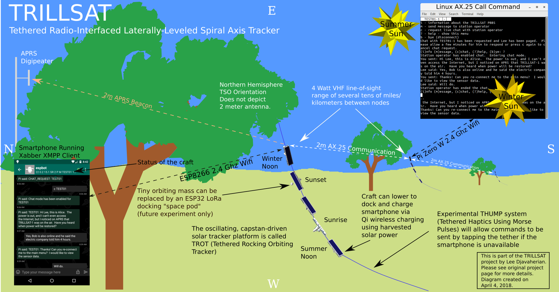
(Click diagram to enlarge)
The Importance of Communicating When You Can't
A few months after I began this project, in May 2016, a strong thunderstorm came through and took down part of our power grid for around 24 hours, and in March 2017, the same thing happened to a lesser extent, and my only communication was via my smartphone to some cell towers (which luckily were still in operation). Those birds that I mentioned took shelter during the storm, and after the storm passed, they flew back to those wires. They didn't care if those wires were energized or not, but they kept chirping, kept communicating. They are mobile, self-powered, self-balancing, peer-to-peer communication nodes.
But back at home at night, I was in darkness, with no heating or a/c, no refrigeration to keep my food preserved. Even my wireless landline telephone was down since many of its systems required power, even though their data lines were still up. All I had was the power in a few tiny USB powerbanks (which I had neglected to keep fully charged), flashlight batteries, my handheld AmateurRadio, and my smartphone. I also had my car, with its gasoline-fueled alternator that kept the lead-acid battery charged and could charge my smartphone via my 12-volt USB adapter as long as the fuel held out. Getting out of that dark house and driving around with the radio on gave me some semblance of civilization, although the roads were often covered in downed branches.
Luckily, I still had those emergency channels, the cell towers were still on the air and not overloaded, and I could still text my family and friends to find out if they were affected, but this would only last as long as my batteries held out. Just checking the electrical company's website was slow and drained a lot of power to determine which areas were affected and what the estimated downtime would be.
I live in a dispersed society in the wide expanses of the Midwest United States in the sense that my friends, family, and business functions are units separated by distances of many miles. Electronic communication and online shopping now removes the need for many of us to leave our homes and meet each other, so many of us keep in touch or do our work via the Internet, e-mail and text messaging.
But when you lose those communication channels, you get a harsh reminder of just how big the world is and just how far away you are. If you lose your water source (which we did a few times due to aging infrastructure) then you have to quickly find some, and the nearby stores will sell out of bottled water quickly. We live near the confluence of two giant rivers which provide us with abundant water, but those two rivers can also flood and meander around my city, essentially trapping us and forcing most of the traffic through the bottlenecks of our highway bridges. This would quickly gridlock and just won't cut it in a major disaster.
Hurricane Matthew hit Haiti in early October 2016, when I was working on this project, causing widespread loss of electricity and communication. I was well aware of this monster, as I was attending amateur radio classes at the time and passed my General Class license exam just six weeks later. Emergency communication is a mainstay of amateur radio, but I have to admit, I'm more the reclusive tinkerer type that likes to work on the systems and electronics; I don't volunteer my time like many other hams do. Instead, I focus on the things I can build, which is still "advancing the art of radio" I suppose, but it is indirect. I greatly value the work of those that provide the direct benefits of emergency communications when needed.
But I began to realize that this project could have solved my entire communication problem, allowing me to maintain wireless texting communication indefinitely, even if those cell towers, the Internet, and the power lines were down; even if my car ran out of fuel. All it needed was a distributed network of crafts like itself (and packet radio and APRS repeaters would help). Of course, the hams have done these kinds of things for decades, but, as far as I know, not in this particular way with a robotic, spiral tracking system and the interfacing of old and new low-cost technologies. It doesn't have to be a ham radio project at all. The packet radio could be substituted with a long range consumer protocol such as an ESP32 LoRa module (which has both benefits and drawbacks, but I wanted to further investigate the old Packet and AX.25 systems that pre-dated the World Wide Web and push it as far as I could, and there are a lot of hams out there that still have the equipment to interoperate with it. I missed out on its golden age in the 1990's as I turned my attention to the Internet--now I want to see what I missed.
The Tree-Climbing "Satellite"
So the idea is to elevate the electronics of a radio communication satellite, not into space, but just high enough above the earth to be useful, keeping the current draw as low as possible, keeping the unit small, lightweight, inexpensive, and weatherproof, and allow it to self-elevate, while at the same time, keeping it out of the shade (to allow for solar power).
One of the interesting things about trees is that they have the same need as this craft--they need to absorb solar energy, and so they branch out to collect more of it, shaping our forests in complex patterns. But they don't just blindly compete, as trees in different situations adapt differently. But in some cases, when competing nearby trees start to block the sun, trees will grow straight up, to get as high as possible into the canopy and out of the shade to collect sunlight. Even a solitary tree may grow tall which will keep its upper branches from shading the lower ones, but a tall tree can also allow more leaves to be illuminated. So trees tend to get very tall, which provides the elevation needed for VHF/UHF line-of-sight radio signals.
One problem with trees is that they block RF energy, and you can't just hang a solar panel on one because it will be in the shade (or eventually become shaded as the tree grows). Leaves are good at absorbing light, which is made up of high-frequency radio waves, and they also absorb some of the lower-frequency 2-meter/70 mm radio signals. So while the summertime produces the most light for a solar panel, it also causes leaves to grow which attenuates some of the signals the radio sends and receives, and this pattern reverses itself in the winter. So it is ideal to get the unit away from the tree.
Fixed-tilt solar panels in the northern hemisphere work best when they are tilted to the south, toward the equator, at an angle usually around the same value as the latitude. In St. Louis, where I live, this latitude is 38.6 degrees.
Sailing a Tether Sea
The tether is one of those things that has always intrigued me. In our material world, we don't seem to have superpowers; we can't levitate objects through psychokinesis, and we can't fly. We can't stretch out our arms like rubber bands and grab things far away, we can't leap tall buildings in a single bound like superman... But, if we cheat a little, and use very thin and long pieces of the material world, tethers, we can mimic that superpower.
As I child, I loved fishing with my grandfather and was a good caster, winning an award at my school camp. But when I was home in the suburbs, I used to tie magnets to string and fish metal objects in my room. Then I started expanding this concept and realized that I could attach motors and lights to electrical wires, and so I drove tiny electric cars (old 1970's toys with dead batteries that my neighbor gave me which I hard-wired) around on tethers. I lowered light bulbs into our storm sewers to look around. I flew kites that I modified with Christmas tree light bulbs and 9v batteries, raising them high into the night sky. And one day, I reached the pinnacle of child engineering and built a message-passing gondola system over my neighbor's house to my friend's 2-story window using hundreds of feet of high-strength monofilament fishing line.
My brother and I loved to swing on our disc swings each day, polypropylene rope tethered to tree branches. We played tetherball against each other for years and became very good at it. And I used to fly electric planes and helicopters on tethered wires, as wireless electric RC flying vehicles were not available during my childhood due to less advanced magnet and battery technology. In cub scouts, I competed in the Space Derby, the "flying" analog to the Pinewood Derby, wooden spaceships with propellers that were guided along tethers. And of course, Spiderman was my favorite childhood superhero, a boy scientist who used chemical tethers to scale buildings. I didn't like Batman as much. Although Batman had his grappling hooks, somehow this seemed inconsistent with his character--he was a bat, not a spider. And in the film E.T. the Extra-Terrestrial, I was well aware that his space transmitter used a tether, connected to a swaying tree, of all things, that produced power...
When I was in my teens, I began designing floating RC vessels that I could steer out on a lake, and fantasized about lowering a camera into the depths (telepresence), but I never continued with those ideas. Decades later, however, I resumed working on RobotDesigns that used tethers, hugely unappreciated machines, often called "winch" or "hoist" robots.
As I started to imagine this project, I wondered, "How do I get the entire unit up into the sky?". I thought about High-Altitude Ballooning, but they don't remain stationary, and regulations won't allow me to just moor a tethered balloon high in the air forever. Quadcopters/drones are noisy and use huge amounts of power. But those birds... those birds just sit on the wires and chirp.
Back to those tethers.
The epiphany occurred after I quickly calculated that at 38.6 degrees in the Northern Hemisphere, a rope tied to a branch high up in a tree can be pulled out toward the southern sun and staked into the ground away from the tree, in perfect alignment for solar panels. And I had just such a tree in my yard, known as the "Tree of Heaven" a tenacious tree native to China and written about in ancient Chinese literature, but semi-invasive in my state of Missouri, the same tree depicted in A Tree Grows in Brooklyn by Betty Smith. I live in an older, inner ring suburb, and this tree probably gained root in my semi-urban environment.
Unfortunately, at low latitudes, the tangent function in trigonometry tells us that the opposite side of the right triangle quickly grows much longer than the adjacent side (the height) if you increase the angle, approaching infinity. So this would only practical at relatively high latitudes. Raising the height (increasing the adjacent side) also increases the length (the opposite side) more than a 45 degree angle. At my latitude, a rope tied 40 feet up will require 50 horizontal feet away from the tree.
Because this rope leaves the tree at an angle, it will eventually leave the shade and reach full illumination if the angle is correct (as long as there isn't anything else higher around blocking the sun). Wonderful, I thought.
So I began designing my craft to traverse an angled tether. Although very different in materials, purpose, and design, it brought back fond memories of Gantenbrink's Upuat-2 robot climbing the mysterious angled shaft in the Great Pyramid of Giza in the early 1990's, since the Upuat, coincidentally, also had to traverse almost the same upward angle and used a rope-climber mechanism. The Upuat was also beautifully symbolic of the mysterious journey of building complicated things such as robots themselves; such a journey is as if you are walking through a dark tunnel of hidden physics until you bump into one of its walls.
But unlike the shaft in the pyramids, a weighted tether can never be perfectly straight, as physics tells us this would require infinite force--there will always be a catenary curve to some degree.
Connecting a rope or synthetic line high up in a tree is not as difficult as it seems. Just tie the end of the rope to a weight and throw it up into the tree. It will often wrap itself around a branch, and if you are lucky, you can lower this weight back to the ground. You can then create a slipknot and pull this up to the tree to secure the line.
Of course, one could also lift a pulley up into the tree to create a "gondola", which could be used to hoist the radio high into the air like raising a flag on a flagpole, but I wanted this unit to be self-propelled and self-contained, so I built a hoist mechanism into the unit itself which would have to be powerful, yet light enough to lift its own weight up that sloping triangle on along its catenary arc.
I soon realized that much of the design problems were similar to the problems that a ship or vessel at sea encounters, as a craft hanging on a 1-dimensional tether behaves in many ways like ships at sea, in this case a sea of rope, and the same types of stabilization techniques can be considered (flywheel stabilization, masts/sails, keels). The vessel does not float in water however, so buoyancy is out of the equation, but it tilts toward port (left) and starboard (right) sides like a ship, and has some similarities to a gondola lift and cable car, yet in this case the cable is stationary and the motor is on-board. But it also shares similarities with "airships", which float in air, such as zeppelins or dirigibles. Instead of a keel, they have weighted "gondolas". It's interesting that they also chose to name the zeppelin undercarriage a gondola when it really isn't a cabled gondola. And zeppelins share something else in common--they hung radio antennae from them, a design now known to hams as the "zepp" antenna, which I explored for use on this craft.
In January, 2018, while performing the final programming, I watched the 2015 documentary Sky Line for the first time and noted similarities to the "space elevator" of science-fiction. One of the engineers even mentioned the peculiar design similarities between spacecraft and underwater craft. And I also built a haptic communication system using the tether itself, so it really is a distinct medium.
I have lived my entire life in the land-locked center of the United States and nautical hobbies are hard to cultivate here, but I nevertheless developed a lifelong fascination with water projects and buoyancy.
I sometimes dream about building a water vessel that could be launched in the Missouri River, reminiscent of the book Paddle-to-the-Sea, reaching the confluence with the Mississippi and making its way out to the Gulf of Mexico. I've also thought about an airborne version, a glider or projectile that is launched and lands from base to base, sending out packets during its brief times in the air.
But at the moment, at least for me, I am dealing with a different medium, a Sea of Tether.
Equations That Haunt My Dreams
Before I began designing the craft, I knew that it would have to be within the realm of feasibility, that the energy and forces I needed would have to be within its design constraints. This was almost impossible for me to calculate ahead of time, due to so many unknowns (strength of my materials in their various structural arrangements, weight of the various parts and subsections of parts, motor torque and speed under various voltages, currents, and loads, friction, algorithmic implementations in various CPUs/languages, interaction with nature). This is also complicated by complex, dynamic interactions that have to be balanced to create a practical application, so I relied heavily on my intuition, creating simple models of various fragments, shaping the design as I went along. I designed in stages, leaving gaps to allow me to calibrate and fill in the unknowns later, hoping they would still be in the ranges that I allotted earlier, making course corrections if I caught them early enough. These gaps were very unnerving as time went by, hoping that my work wouldn't be in vain. In retrospect, I wish I would have paid more attention to certain details, but, again, it was impossible for me to know ahead of time what those details were (out of the hundreds) that would later become the most important.
I knew early on that there were several science (physics and even information theory) equations that could come back to haunt me, but I underestimated the sheer number that I would have to familiarize myself with, many of which I haven't revisited since my college years. Equations are relationships in a language of mathematics, and relationships (relations) are how human knowledge comes into existence. Without relationships, we would see the world as random, meaningless.
I studied basic physics (mechanics and heat) and the higher maths in high school and college in the 80's and early 90's, and used some Linear Algebra at work, but I never had a reason to really apply abstract physics or math concepts at home (although I did take a couple of classes in complexity mathematics in recent years). So I knew about force, mass, vector resolution, trigonometry, and differential equations, but they are by no means my strengths. And I had forgotten all about those parametric equations from calculus...
The most obvious equations were:
- Static equilibrium of 2 ropes and a weight (similar to the weighted catenary equation with 2 ropes at different heights and angles lifting a weight above the ground)
- Capstan (how to size a capstan to create friction needed to hold a particular force)
- Torque (finding the force based on radius for my capstan and rotating motors)
- Gyro angular momentum (how to compute the inertial forces of a gyro based on its speed and mass)
- Pendulum (finding the period of swing based on length of the rod)
- F=ma, Newton's Second Law of Motion and its related centripetal force equation
- Center of mass (for balancing)
- Various electrical laws (output of solar panels vs. power needed for radio/electronics/motors vs. storage capacity and output currents)
- Algorithms that have to work within time and space constraints of the CPU/microcontrollers
- Work, power, and thermodynamics (the sun is hot, the winter is cold, information processing/motors create heat; heat radiates, conducts, and convects, but components/materials are only designed to work within a specific temperature range)
- Lambert's cosine law and other optical equations (for computing solar efficiency at various angles, and sun position using LDR)
- Hooke's law (for making estimates about the elastic behavior of the tether, panels, and planetary rod)
- Trigonometry (for kinematics, parametric equations, trochoid and cycloid paths through space, oscillations, changes of angles, the hyperbolic cosine "catenary" and its fascinating relationship to e)
Did I get out my pencil and paper and setup the problems and do the calculations? In most cases no, I bounded a lot of the concepts and used my intuition, knowing that those perfect solutions were in there somewhere, inside those bounds, but I'd never know exactly where there were unless I did a full analysis after the fact. The human brain is a great tool for allowing us to do this--it can get us close, like Captain Kirk, but most of us can't satisfy the precision of Mr. Spock.
I knew that the craft would have to be light enough to pull it high in the air, the capstan would have to be able to withstand significant compression, torsion, and shear stress, the motor/gearbox would have to have significant torque, the gyro would have to either spin very fast or be fairly heavy, and that I would have to balance the craft carefully. But I also knew that the power usage for the various line-of-sight radio transmitters at my frequencies would have to be relatively high in order to function over a wide geographic area without a lot of nodes. I love the idea of amateur radio low-power "QRP" but decided on a fairly old, inefficient, and inexpensive packet radio digital mode to be practical and work with existing systems/packet networks.
The system is experimental, but it is an experimental design intended to be a practical system, as I like to build systems, servers, things that do work for us and am not captivated by analysis or data gathering, which I'll expand upon later.
But as the project went on, it was luckily barely in the ranges needed to demonstrate all of the concepts that I tried to cram into it, and the question of whether some of those things I bounded were outside of my bounds began to haunt me, and I felt like Kirk alone in his ship, far from his friend Spock. Some things work well, some not so well. But that's why it's TRILLSAT-1, my first prototype. I don't know if I will ever build a second, but it will take years of additional refinement to reduce weight, improve its balance and motor algorithms, and create a more robust and weatherproof frame. There are some short-term modifications that I can make to balance the craft properly (as I explore at the end of this essay), but I wanted this craft to represent my original vision.
So it is intended to serve as a proof of this particular arrangement of concepts, an arrangement and design that fascinates me. My father, for example, built a few musical instruments in his life, his visual designs being quite beautiful, but, he couldn't perfect the sounds that emanated from them. It is difficult to find that optimal balance of competing constraints, as our individual strengths are usually concentrated into a few, but not all areas. I found that most of my time was spent on the things that I was least experienced with, trying to get those things up to the same level of quality as the things that I had already mastered, and this was as close as I could get on Attempt Number One.
Keeping Costs Down
My primary design constraint was to keep the costs down, not only for my sake (as I don't have a lot of disposable income) but for the sake of learning, education, and fostering excitement in electronics and adding to the wonder of the world around us. When costs are low, things become available to the masses, and one can afford to experiment and break things. Almost anything can be achieved if you throw enough money (and thus manpower) at it, but this is often a hasty approach that misses the point, leaves tiny things overlooked, and you miss the craftsman's journey. You miss the opportunity to teach yourself something new about the Universe. When you start such a project to build a new "object", something that has never existed in the material world, to me, the point isn't to create that object at all, the point is to understand it, to understand how it fits into the natural laws of the world, to understand why the natural world allows such things to exist (or not exist), to understand our limitations in Time, Space, and Energy, and to dissolve any delusions we may have had due to our assumptions.
Luckily, at the time of this writing in 2018, we live in a golden-age of low cost electronics, and there is so much information available that you could spend several lifetimes and never fully understand all of its forms. And 3D printing now allows us to more easily experiment with the mechanical world, too. Have you ever noticed how amazing toys are? Many children's toys are extremely good teaching tools, and even as adults we still don't have all of them understood. They encapsulate ideas and concepts, the real magic within our world.
So the first thing I decided was to use 2 inexpensive WiFi-capable CPUs (Raspberry Pi Zero, which I later replaced with the Raspberry Pi Zero W when it was released, and the ESP8266) and then later incorporated 2 more (the ATtiny 1634 which is under 2 US dollars each), and all of the major parts would be designed with Free and Open-Source Software, printed on an open-hardware based 3D printer (the cost of bulk plastic being fairly low), and then programmed it myself. I relied on many different communication protocols, such as a hardware and software UART (reminiscent of my old C64 days), and the more recent I2C and 1-Wire protocols. I built my own systems, too, programming my own XMPP server, Morse Code decoder server, and an AX.25 PBBS server and APRS client. I chose to use a popular Chinese amateur radio transceiver, which was one of the least expensive available (using DSP in-place of analog radio circuits). I didn't use expensive pre-etched PC boards, but simply wired point-to-point "dead bug style" on generic boards or glued the parts directly to the 3D-printed substrate. I built as many circuits as I could where practical, using low-cost circuit designs and common electronics (the 2N3904 transistor was used throughout, for example) which removed the need to buy as many custom interface boards or chips (I built my own packet radio interface, my own high-power H-Bridge, etc). For major things like the solar panel, batteries, ball-bearings, DC-DC boost converters, and Qi charger, I decided to buy Chinese parts online, since the US equivalents were simply too expensive, but the internal solar cells and some IC's are American and the Lithium-ion cells are Japanese. However, after I had already purchased the parts, my country placed import tariffs on solar panels and aluminum, so it is unknown what the actual costs of these parts (or their equivalent) will be in the future.
China is in a golden age of tech manufacturing that reminds me of my country, just after WWII. In the 2016 documentary Shenzhen: The Silicon Valley of Hardware they show huge DIY parts stores that allow individuals to rapidly prototype just about anything. We have nothing like this where I live (and our largest electronics parts store chain filed for bankruptcy while I was working on this project), but I am lucky to have a local electronics store called Gateway Electronics that still offers individual parts in bins that can be browsed and examined. My country still has some very sophisticated and high-quality integrated circuit companies, however, but the chips go straight from the factory into surface-mount consumer electronics and the individual tinker/prototyper is often overlooked. This is where China excels, yet the trade-off is in the documentation. Many Chinese integrated circuits have no English language datasheets whatsoever. The maker movement in my country is adapting to much of this, and many new-generation electronics/robotics stores are now available online with many good teaching resources, yet this comes at a slight premium. So I bought the bulk of my electronics from large distributor warehouses in Minnesota and Texas.
I went to big-box home improvement stores to find cheap raw materials and bolts/nuts, mostly Chinese, but some from the USA and other countries, and for the really unique stuff, I had to disassemble consumer products, re-purposing them.
But even after being very careful to keep the costs low, the sheer number of parts nickel-and-dimed me to the point where the total cost ended up being around $390 US, larger than I expected.
Repurposing Household Products
Repurposing is a rather new word and wasn't used when I was young, but it has recently become a very popular term since the maker movement of the 21st century took hold. I was 10 years old in 1980, and so I acquired a lot of 1970's-era "hand-me-downs" from neighbors, a term that was often used to describe second-hand items. Around the turn of that decade, people had tired of crafting, the peak of the macrame fad had passed, and consumerism was ramping up again. It didn't matter if an item was of inferior quality (which many of them were), but as long as it was purchased from a manufacturer with a brand name, you were cool. I witnessed this firsthand--I would hang out with my neighbor during the day and beg him to play with his mass of cardboard boxes full of unique and creative '70's-era games and toys (many of which he acquired from his older siblings that had moved away), but they were passe. Peer-pressure was forcing us all to change--if we didn't wear name-brand clothing to school, we were ostracized as being backward or poor.
I was one of the kids who didn't grow up with as much money as the families around us. My father owned a discotheque for a short while during the late '70s, and for a time, I used to wear the biggest hand-me-down bell-bottom jeans in my elementary school, like a little Six-Million Dollar Man, but I didn't get stuck in the 70's for long. When British New Wave music and 8-bit computers arrived, I realized, this is a really cool time. I bonded with the '80s, yet will always miss the simplicity and warmth of the '70s. The '70s wasn't just about style, however, it was full of substance. My father was an audiophile and built a quadraphonic stereo system for his discotheque, which was ahead of its time. Four-channel sound wouldn't be appreciated or understood by consumers until 3 decades later--the home-theater/surround sound movement of the 2000s. For substance, the '80s was a dark age where style ruled supreme.
I also have an interest in film, and if you watch some of those coming-of-age 80's American films, you'll see that they frequently depict class divisions, the cool kids with all of the new products juxtaposed with the poor kids that were stuck with old things from the 1970's and couldn't move out of that decade. This was all too true.
In 1987, we visited my cousin for Thanksgiving who lived in the affluent Chicago suburb of Highland Park, and she drove us to a party (while the Men Without Hats, Pop Goes the World was playing on the radio). Although she lived with her parents in modestly small house, the other houses in her neighborhood were essentially Gatsbyesque mansions, many still containing separate servant quarter buildings from the last century. We drove past the houses where Risky Business and Weird Science were filmed. I asked her about her public high-school and was shocked to find out they had carpeting and a pool, which mine had lacked.
What I saw in that place and time was just like those films. John Hughes captured this suburban class divide in a lot of his films (and shot many of them in that city such as Ferris Bueller and Sixteen Candles).
After that day, I realized that, films, while large part fiction, are always connected in large-part to reality. Whether it is art imitating life, or the other way around, it didn't matter--there was a connection. I later studied film in college, realizing that its power was far more vast than most people realize, and in recent decades I've been philosophically deconstructing such concepts. Fictional stories and factual "hi-stories" are identical in pattern, structure; only the inputs, the details, vary.
Since my family didn't have much money in the '80s, I repaired a lot of things around the house (and the neighbors' houses) and felt like the kid in The Last Starfighter. I repaired our washers, dryers, sinks and toilets, air conditioners, automobiles, wired my neighbors' telephones, put chips in computers, fixed people's projectors, radios and televisions. It was sometimes an annoyance, but there were those times, working with my father and grandfather that were special when we tried to fix our old, sometimes poorly made, machines, furniture, or tools.
This was especially significant with my father, as English was not his native language, so we had trouble communicating complex ideas (he often used allegory and symbols), but when we had a machine open (often engineered by people of countries foreign to both of us, using methods foreign to both of us) and were trying to figure out how it worked, the geometric shapes, the spatial relations of the parts, the varying forces were a universal language that transcended our limited words. It was those times that we saw the same things and knew that each other shared the same things. So something as trivial as fixing household machines, in retrospect, was profound.
My father grew up in a world of wood, metal and radios, but I grew up in a world of plastic and computers, some of those 70's hand-me-downs I often re-purposed for my projects, so I frequently saw things fatigue and break, warp and discolor, melt, etc. One of my earliest childhood memories is when my brother and I sat in our green, molded plastic chairs at a little round table where we used to draw pictures, close to the gas oven in the winter, since it was warmer over there, and my brother suddenly started sinking in his chair as it melted. Observing these materials during my formative years unknowingly helped me develop a language of the plastic (polymer) medium which I didn't realize until I built my first 3D printer in 2015.
In 1980, the film My Bodyguard came out, also set in the Chicago north-side. I had read the book by Joe Claro before I saw the film, and loved it. Linderman, played by Adam Baldwin, was my favorite character. Not only did he stand up to bullies, he was poor and built his dream motorcycle piece-by-piece from used and discarded parts.
E.T. came out in 1982 when I was 12 years old. Hughes captured the class divide, but Spielberg captured a different feeling of the 80's American suburbia, a feeling of wonder. E.T.'s transmitter, by the way, was an assembly of "repurposed" consumer products.
So for this project, I used 12 different consumer products in interesting ways:
- Black & Decker AS6NG cordless screwdriver (main drive motor and planetary gearbox)
- Lite-On LDW-411S DVD-ROM (BLDC 3-phase spindle motor for gyro/fan)
- X-Dragon 14 Watt Solar Charger (main power source, contains two 7-watt solar panels with Sunpower cells and a 5v regulator)
- (2) iKits PBM-G-G102 Power Banks (power storage and charging, 20400 mAh total, contains 6 Panasonic NCR18650B Lithium-ion cells and charge controller/boost converter)
- Baofeng UV-5RA Radio Transceiver (I essentially turned it into a packet radio TNC by building an interface, controlling its flash, PTT, and LCD display programatically and adding software modem)
- Syba SD-CM-UAUD USB Sound Adapter (for Bell 202 AFSK tone generation for the packet radio)
- Earbud headphones (contained small rare earth magnets that I used with 2 digital Hall-effect sensors)
- Slingshot shot (for gyro weights)
- Daisy steel BBs (for planetary weight/damping)
- TOMOL Super Bright COB LED mini flashlight (removed 100-lumen white COB LED board to use as spotlight)
- Old kitchen cabinet (removed 4 Amerock Self-Closing Hinges and added them to the Ark door)
- Blueberry produce container (cut to create clear plastic PET rain covers for the tiny LDR Tubes)
Hacks
While re-purposing is a 21st-century trend, I am still a product of the 1980's movies like Wargames and Real Genius, and being a kid during the microcomputer generation, I never grew out of the need to show off my ingenuity, so this project wouldn't be complete without a series of hacks↗ as well.
- UV-5RA flash programming for frequency and LCD control
- Building an XMPP Server on the ESP8266
- Incorporating my Morse Decoder
- Virtual UART and bypassing Raspberry Pi hardware I2C bug
- Sending a beacon on the APRS frequency while AX.25 sessions are in progress on another frequency using a single tuner
- Writing an AX.25 BBS using Unix techniques
If you can master construction, deconstruction, and finding hidden paths via logic and experimentation, you have access to knowledge and bring your dreams into existence. Linderman can build a motorcycle, E.T. can send a message millions of miles away to his home people, so surely I can build a terrestrial analog of a spacecraft. Perseverance and wonder is all I need.
A Space-Elevator-Spacecraft
In 1945, writer Arthur C. Clarke first proposed the concept of "Extraterrestrial Relays", which today we call the geostationary communication satellite. While he is remembered for his authorship of science fiction, such as 2001: A Space Odyssey, he is not always remembered for his earlier work as a radar specialist in the RAF and later work in mathematics, physics and space exploration.
Today, modern technology makes it possible for people to create their own communication satellites, such as the CubeSat↗ project, but even today, it is still expensive for individuals. Even before CubeSats, hams were building OSCAR↗ satellites. And in many ways, today people can now easily control their own spacecraft. The modern telepresent and telecommanded quadcopter drone is one example, equipped with a camera and different types of sensors, motors, and radio equipment. The only difference is that the planet they are exploring is Earth (terrestrial), and not one more distant with a different gravity, atmosphere, weather, and temperature (extraterrestrial). Today there are a variety of inexpensive tiny microelectromechanical systems, MEMS↗ sensors that used to be large, expensive, and in the domain of the aerospace industry, such as accelerometers, gyroscopes, magnetometers, and inertial measurement units (IMUs). This is post space-age stuff, and the main hurdle preventing people from building real spacecraft is overcoming that extremely fast escape velocity of approximately 25,000 mph (40,000 km/h). To get something into space, it has to be launched at approximately 33 times faster than a speeding bullet and the speed of sound, Mach 33.
But my design goals were neither to create a robust radio station nor re-invent the drone--there are a variety of better ways to do this. I wanted to create something that was small and self-contained, something that emulated an actual satellite or distant spacecraft, and do it with extremely low cost. After deciding to raise the entire station into the air, I had no idea at the time that it would begin to share similarities with the space elevator of (at the time of this writing) science fiction.
Thirty-four years after Clarke proposed his relays, in 1979, he published The Fountains of Paradise, being one of the first descriptions of a space elevator↗ that most people had ever read. It's strange how obscure this idea remained during the 20th century (and even today). If built one day, the benefits will be enormous. Unlike my craft, however, a real space elevator has to have an unbelievably strong tether, has to travel a lot farther, but could also take advantage of centripetal force that counteracts gravity, the elevator getting lighter as it ascended at a rate that exceeds the inverse-square law. I thought about creating a sort of counterbalance in my initial designs, before I settled on the capstan drive, using the mass of a weight with its pulley attached to a tree branch to pull the weight of the craft upward, reducing the energy needed for its drive motor (like a garage door opener, for example)--but this added more complexity and external dependencies to the craft.
By the way, this capstan-driven craft cannot actually traverse a space-elevator tether. The tether would be large and the tension would be immense and immediately disintegrate the capstan and crush the frame. You'd have to build a crawling/climbing style mechanism, not a wrap-around capstan. But the same issue that prevents its use in a real space elevator is an advantage at lesser forces. The capstan can withstand tensions/compression that might be too much for a standard winch/takeup wheel, as the strong forces pulling at opposite ends to raise the craft are redirected at the capstan. This is why you'll see heavy and powerful capstan winches and horizontal windlasses in industrial operation, and large hydraulic ones in use on ships. The mechanism is simple and has less moving parts. And they don't have to deal with reeling in and out a spool of tether which changes the weight/balance, the radius, torque, RPM and tension calculations, and the space needed for storage.
A craft like TrillSat, if hardened for the conditions of space, could also orbit the earth and still work for a reasonable period. The International Space Station, for example, uses similar consumer technology↗ (AX.25 packet radio on a low-power transmitter) to communicate back down to the surface. At the time of this writing, they have two 5 watt Ericsson HTs on-board in their Columbus module, and I am designing mine around a Baofeng UV-5RA 4 watt HT.
Elon Musk's Tesla Roadster and Starman driver was launched aboard the SpaceX Falcon Heavy on its test flight on February 6th, 2018 (which I watched live via Internet stream) while I was building the TRILLSAT-1 Ark and Test Frame and it wasn't even space-hardened, yet it is now orbiting the sun like a tiny red planet. But just as fascinating to me is that there is also a tiny toy car on board, traveling through the solar system. A car within a car, self-similarity.
Is TRILLSAT-1 a true spacecraft? It depends on your definition. Are the Apollo or Mercury capsules spacecraft? Today some of them now sit in museums. They don't orbit the earth, but even today, they do still orbit the sun, they just do so from a low earth altitude. No man-made object has ever left the gravitational influence of our sun, captured by the primary influence of another star. It will be many thousands of years before this happens to Voyager 1. The Earth itself is a spacecraft. But perhaps those lonely wanderers of the interstellar medium, like the timeless Voyagers, are the "true" spacecraft.
This project incorporates a lot of my interests: computers and robotics, vending machines, vessels and self-contained machines that survive the elements, and, of course, communication systems. Successfully communicating with an autonomous entity somewhere else in space and time is fascinating, and if the machine is alone, somewhere off in earth's wilderness, it is tremendously exciting; a lonely, ancient sentry, always on duty to send us a courteous reply when asked, like a tower cathedral for an old monk friend living his life in solitude while still carrying on functions to assist humanity. Like Spock, he doesn't have to be fully human, just humane.
This is also an attempt to coexist with Nature, creating a crude entity that reminds me of that bird on a wire, but I also borrowed ideas from the Tree (photovoltaics in place of photosynthesis, move slowly to track the sun, materials that create the desired infrared (heat) reflectivity and emissivity, redirecting the flow of water, etc). It will need to contain its own power storage and will derive its energy from the Sun. It will also have zero reliance on the Internet or mobile cell infrastructure. It will encounter clouds, wind, rain, hail, ice, snow, and animal life. It will have to compensate for both the rotation of the Earth (day/night cycles) and also its tilt in relation to the orbit around the Sun (height of the Sun in the changing seasons). It has no real-time clock, so it will ask us for the time of day or pay attention to solar noon. It will have to overcome the curvature of the earth, since it uses line-of-sight radio frequencies. It will need to incorporate failsafes, manual overrides, and redundancy since it will be difficult to reach if a problem occurs. It will contain multiple radios for different functions and will use a low-bandwidth link (1200 bps) for long-distance communication so data transfers will take time, which simulates the operation of a distant spacecraft with weak signals (except that there is no significant latency created by the speed of light). It will contains its own gyroscopic inertial stabilization and reaction wheel, and it will be "orbited" by a planetary "space pod" in complete electrical isolation from the rest of the craft, like Dave Bowman leaving the Discovery One in 2001: A Space Odyssey, reminiscent of the human centrifuge tests of NASA astronauts, a cyclical movement that mimics the planetary pull of gravity, even using gravity to change the attitude of the craft, that can dock and undock at will. It evokes the exciting VertiBirds↗ of my youth, round and round, flying on a rod, while balancing on a tether.
The craft is a Fractal microcosm of itself.
Design
Invisible Forces and Fractal Self-Similarity
There is a point in the design of a machine where my subconscious decides something is optimal, and I know intuitively when this point arrives as I sense a multiplicative gain in a surprising way, sometimes I sense several. Often the search for these gains begins to shape the project in a fractal, self-similar, and recursive way. It is likely that something engineered to work in the real-world becomes fractal, as fractal shapes are often the results of optimization around a complex set of constraints, but it's not the whole picture. Our minds are also fractal cathedrals, spaces consisting of wondrous halls and twisting catacombs, shaping our very recognition. When I'm on the correct path, the gains assert themselves time and time again. When I'm not on the correct path, they are few and far between. Nature may abhor a vacuum, but it adores fractals.
Have you ever stared at Jackson Pollock drip/pouring-style painting for any length of time? We have one at our local museum, and the room was empty one day, and I had a chance to stare at it by myself for several minutes. It's quite a different experience to observe it for a length of time than to just walk by and dismiss it as random noise. The longer you observe it, the more interesting it becomes. There is a fractal hidden within it.
This is not to say that any design is the right one. I learned in my earlier designs that there is no perfect design and there is no bad design, each design has its unique place in Nature. But fractal designs can be very efficient for my uses as they provide me, personally, with more benefits than I would likely otherwise see in my life--but this is just my subconscious can see the shape, it is within my capacity. Another exotic design that might appear alien or inappropriate to me may down the road be preferable, but I simply lack the context and awareness to realize it. So I rely on my subconscious to remind me of these larger patterns and guide some of my decisions. Inventors, such as Edison, have intentionally induced a hypnagogic state to do this, but, while working on my film project years ago, I learned that such a state is not needed--the ideas will assert themselves when they find an appropriate time. Time is part of the equation, and our conscious mind cannot see into time, it cannot see your personal Zeitgeist, but your subconscious can.
Perhaps most mysterious to me is that I had written about such a robot years ago at the beginning of the millennium: the main character in my screenplay had built a device with almost the same core specifications: solar charging in cyclical fashion, separate microcontroller core, internal gyro, camera, balance algorithms, reset network, surrounded by a spiral or helix, discovery of bugs, a wooden rectangular storage box and central pole, interaction with birds, and control via "texting" before SMS was even in common use. But like a dream, the details were different.
I tend to get very philosophical in my writings, examining ontological and metaphysical concepts, and this "technical work" is no exception. Did my mind conceive of a symbol that I obsessed over and tried to make real? If so, how could it have conceived of a "functioning machine" as I would have no way of knowing if the machine had actually worked or what its purpose would be until I built it? Is this the awesome power of the subconscious? And this complex combination did work. Or was it simply a lens into a future worldline where I saw something I had already created and then, in cargo-cult fashion, simply emulated that thing? Since how would I have accounted for the actions of other people, that lived their lives independently of me and suddenly matched certain sequences in my story?
Besides Edison, if you look at creative inventors like Arthur C. Clarke or Nikola Telsa, their work had very odd characteristics. And Albert Einstein is one of my heros. How is it possible that Einstein's intuition was so accurate without experimental verification? Mathematics, when aligned with reality, can lead you to thousands of destinations if you have no physical signposts--how did he know which path would be the right one?
It's curious that I seem to repeat myself, building essentially the same type of system in different ways and never tire of this. What are these invisible forces compelling me to create such an object? I seem to be seeing/feeling a particular shape or geometry that is difficult to explain, but I have no idea "where" it exists. One thing I've learned about myself is that I seem to build things according to a power law↗, that once I learn the core principles or rules to a system, if I am intrigued by them, I make an attempt to ramp up the difficulty/complexity on my next project, as if I'm trying to see a magnified expression of these rules. Interestingly, this new design took me down the path of "real" invisible forces such as gravity, inertia, and inductance. Rather than design a gear/lever system to tilt the solar panel, the orientation of the drive motor causes a shift in balance, rather than use extra stabilizing tethers a rotating inertial mass inside the craft was chosen. Rather than connect to an external power port, wireless inductive charging was used. Rather than plug the unit into a wall socket, it receives its energy from a star millions of miles away. And in many cases the motion of the motor had additional, overloaded functions (the solar panel tilt also drives a capstan winch and tilts a light and camera, the gyro is also a heating/cooling fan and reaction wheel, the power port is also a planetary pod docking base, the same MISO line is used for the light, programming, hall-sensor, and Morse communication, etc).
What the heck am I talking about?
Firstly, the craft is designed to operate in a very "fractal" environment, suspended by trees, absorbing power from a cyclical sun with passing clouds, withstanding weather (which is chaotically fractal), and has to be high enough to provide line-of-sight (and adequate radiation patterns) above fractal irregularities in the surrounding terrain. It is "arboreal" in the sense of something inhabiting a tree, yet it also fulfills the second definition of arboreal, that it is of the tree, it is like a tree.
While the machine is not organic, like a lifeform, it turned out to be very fractal-like in other ways, containing branching, complex self-similarity, but also containing elements of recursion, symmetry and inversion.
I'm a Logician, not an Analyst
Even though I like to analyze my own creations (which is really a form of comparison), throughout my life, many have incorrectly assumed that I was an analyst, scientifically-minded, that I tend to "over-analyze" subjects and have a need to dissect things in order to understand them. It is easy to make this mistake, as my interests are in many cases the same as in the science and engineering fields (finding or pushing up against the boundaries of the natural world), but there is a subtle, but very important distinction: I understand the world through creation (modeling) and comparison, and I don't get any enjoyment at all from dissection and measurement (what most people consider to be "scientific" analysis). My tools are reason, rational thought, and logic, and I use high-level comparison. I choose rationalism over empiricism, as I believe the mind is a better "measurement tool" than our artificial tools.
So I tend to avoid using measuring equipment in my work. Instead of finding precise boundaries, I stay well within the bounds of those lines and take advantage of logical inference of the inner machine created within. I don't use an oscilloscope but get by with multimeters or math calculations, yet I even forgo those tools, too, in lieu of my precious theoretical and experimental models, to "try it and see if it works" first, leaving any error checking for later... It can be pretty crude, I admit, and I do appreciate the people that do the hard work to gather and analyze the data that I don't, but my view is perhaps understandable since one of my greatest fears is that I will get stuck in the abstract, mental world forever, always measuring but never getting a chance to transfer my inner ideas to the physical world, like unmanifested, lost Dreams, a sleep from which I cannot awaken. The line between the real and the imaginary is old and faded, so I have to periodically wipe away the dust.
So I tend to operate very differently than scientific researchers, whose career is full of empirical instruments, statistics and graphs. I also purposely don't introduce the rigor of an engineer. Instead, I focus my time/energy/knowledge to maximize my own understanding of the world.
Improving Upon My Earlier Projects
I took what I learned from my earlier OswaldBot and PacketRadio projects and improved upon them. The former is a Python 2, XMPP-based home automation robot running on a Raspberry Pi B+, the latter is a packet radio interface for a Baofeng UV-5RA running on a Raspberry Pi 2. I also taught myself Lua for this project so that I could easily incorporate an ESP8266 running the wonderful NodeMCU.
To reduce cost and power usage for this project, I used a Raspberry Pi Zero W and a Syba SD-CM-UAUD USB sound adapter instead of the Pi 2 and UCA202 which I used previously. I changed the Python GPIO module from RPi.GPIO to Pigpio, changed the software modem from Soundmodem to Direwolf, and I had to bypass Prosody and Chirp and write my own XMPP server and UV-5R programming code. I also changed from a hardware to software UART in one case.
I applied better event-driven programming practices as well, to keep the CPU/power usage low and to prevent communication deadlocks. I could no longer rely on my lazy, brute force loops.
Lessons from My Father
My father was a designer, not by profession, but by natural ability. He was many things, all largely unrecognized within the time he lived: artist, inventor, audiophile. He was even his own Stradivarius, not an Italian musical instrument woodworker and craftsman--he was Persian--but he was also a musical instrument woodworker and craftsman.
His best creation, in my opinion, was a beautiful santur↗, a Persian percussion-stringed instrument using walnut wood and coconut shells. For weeks I watched him build it, and curiously, TrillSat, my hunk of plastic and silicon, is about the same rough dimensions and weight. Now that I think about it, the santur is also a "quantized" communication machine, being a "hammered" dulcimer, but it emitted warm sound, not cold, packet radio signals. But he might have liked my project if he was alive to see it, as he once assembled a 4-channel audio system in the 1970's, years ahead of its time, building the speaker cabinets from scratch and wiring the crossovers, and he loved shortwave radios. TrillSat, in a way, is a "string" instrument, too.
I have pieces of his mind, contain fragments of his perfectionism, but don't hold the entire key. I can see into the world of my father yet am more distant from it and have a more difficult time reaching it. My father made attempts in his life to bring "perfect" things into the material world from another, perfect, world, an ideal world that he could only reach in his mind.
He also mirrored this in other ways, trying to bridge worlds. He built a discotheque in the 1970's and a few years later tried to start an import-export business, transferring objects between different worlds, until his country's revolution crushed any hope for that dream.
And because he came from a different culture, he had different customs, and while he couldn't always transfer "objects" between two very different cultures, I sometimes witnessed him transferring "magic" instead, his knowledge.
One of the most memorable experiences was a kite he built for me. Within the span of around 30 minutes, he built a flying kite out of wrapping paper, glue, and a thin wooden stick unlike the designs in my country. While my childhood books were full of the traditional "diamond" style kite, he built an Indian "patang" style kite, a square kite with a curved bow, and it flew wonderfully.
My father had a mercantile mindset and chose the best designs of those available between cultures, appreciating the best goods and products made in the world, regardless of where they came from, not limiting himself or fixating on any one people or culture's traditions. He also switched between languages, often using the particular word that was most representative of an idea, regardless of its language of origin. And design was more fundamental than culture, it was universal and underlying, and this topic also provided a way for us to communicate with each other, as I mentioned earlier, as we could see the same thing.
So I learned to see design as a way to express one's freedom, that the constraints weren't one's culture, they were form, shape, efficiency, natural law. But, unlike my father, I was slow to know where those bounds were, gaining most of my worldly knowledge from American books which often didn't tell me whether or not this knowledge was a best practice, convention, or whether it had fundamental limits.
Thanks, Dad, this is my kite.
Finding the Right Design
I didn't design the craft until I had first built the new radio interface and programmed the AX.25 PBBS code, as I had to confirm that I at least had something useful to hoist into the air, or there was no real purpose for the robotic platform at all. I only enjoy experimenting as long as I know that there will eventually be a tangible benefit. Knowledge for its own sake is, by definition, useless and perhaps even an outright illusion, keeping us in a state of perpetual inaction. But once applied to our physical world, knowledge becomes an invaluable thing.
It took approximately one year for me to program the radio and PBBS (2016), and one year to design/build the robotics (2017) and perform basic programming of the microcontrollers, although the final programming has gone into 2018 and it will take even more time to perfect the algorithms.
I have several notebooks containing my sketches and notes over this two-year span, along with my Internet blog, that documents the evolution of my design, although I had kept the details secret until this article was published. As I tend to prefer, it was all thought-experiment except for a few models that I made out of pencils and twine to confirm the final concept, and I have to admit that rotating the parts around in OpenSCAD later helped me eliminate a lot of problems before they ever reached the physical stage. I wanted to create a smaller and cheaper radio audio/programming interface and add smaller computers such as the Pi Zero or the ESP8266, as I mentioned above, but there was no real reason to make them smaller unless the unit had to be lightweight, low-cost and low-power--a solution in search of a problem, and if this was possible, this opened up the idea that the entire base station could be raised into the air. Before those red-winged blackbirds inspired me, I started to pay attention to High-Altitude Ballooning, which led me to take a closer look at APRS, which I had previously ignored. This is a fascinating hobby, but there is a transience to it that disturbs me--besides the FAA regulations, the balloons eventually float outside of useful radio range and are intended for short-term testing or data-logging. But again, I'm not an analyst--I don't enjoy capturing or analyzing data, but I want the craft to do something. I like to set up servers more than sensor networks.
I needed to get it high above the earth, so my next idea was to design a pole-climbing robot, and I spent several weeks trying to come up with a simple wheeled mechanism that allowed the unit to drive up and down a pole that might serve a dual-purpose, such as a purple martin birdhouse or flagpole, both of which another of my childhood neighbors once had in his yard.
But friction became a problem. The friction needed to hold the wheel against the pole had to be great enough to overcome its weight, so I couldn't use weights themselves to apply more friction unless I added long levers and would need a more complicated spring mechanism. And I didn't want to spend months of mechanical engineering/prototyping a gripping-style or hand-over-hand climber, either, and insisted on the simple wheeled design. Since I've designed various winch bots in the past (but never actually built one until now) I decided to instead use a rope tied to the top of the pole and winch the bot up and down--problem solved. But now the entire point of the design was lost--here I have a pole and rope that need to be erected first; it might as well be an antenna mast and guy wires, standard radio equipment. Heck, there's no reason to even create the winch at all, just mount the craft at the top of the pole and be done with it... But I wanted a spacecraft.
The birdhouse idea, though, kept me thinking about those red-winged blackbirds sitting on wires, sitting on tree branches, reminding me of my childhood tree-based message-passing gondola system, and I realized that what I really needed to do was winch/hoist the entire craft into a tree, and trees have been used by ham radio enthusiasts for years as antenna supports. As I mentioned earlier, I did the calculations to confirm that the angle needed for a solar panel at my latitude could in practicality become the angle of the rope itself and the sun never goes behind the north side of the tree in my hemisphere. Now I was intrigued. Yes, it would be subject to sway and rotation in the wind... now I have the opposite--a problem in search of a solution.
But my early designs varied between a traditional on-board winch (with a take-up reel) and a capstan winch. I didn't want to create a gondola lift, as then its propulsion would be controlled by an external "bullwheel" and wouldn't be self-contained. If I used two traditional winches, opposed to each other, they could also "land" the craft at various places and control their own rope tension, but this required 2 powerful motors, tension-monitoring sensors, and dynamic calculations of the torque of the two spools. As one spool collected the tether, its diameter would increase, lowering the torque and requiring it to slow down to match the other spool which was losing its tether, decreasing its diameter. Another issue was locking the spools--if the gears weren't locked when the motors stopped, the rope tension, which is very high, would act like a lever on the large spools from the weight of the craft, and it would simply cause the motors/spools to unwind and the craft would come down.
I could have used a hanging weight in the tree to overcome some of craft's own weight, getting by with just one spool, but it meant that an external, "out-of-band" mechanism was required, and I wanted this thing to be self-contained and autonomous like a spaceship.
The capstan solves these problems--it solves the locking problem, the torque, weight, storage, and changing RPM problems. It doesn't require tension sensors or take-up reels, but it does require proper rope tension, capstan design, and friction on the capstan, and it can do it all with just a single motor.
Now, how do I orient the capstan along the tether: longitudinal, transverse, or hanging downward? I immediately thought transverse, like a front-wheel drive car engine, allow the capstan to balance and "roll" along the top of the taut tether. In this case, the horizontal capstan would be called a "windlass", but balance was a problem, so I decided that I would have to add a hanging weight to change the center of mass underneath the rope. But when I decided to add the mechanism to tilt the solar panel from the same motor, add the rope guides and keep water out of the horizontal motor, the complex mechanical problems became apparent.
Next, I explored longitudinal, and this had many benefits, and the craft began to take on the shape of a cordless drill or gun. Think about this: a pistol or cordless drill is something you point along one axis while allowing rotation along the same axis while maintaining that fixed point. This works very well if your axis is the tether since the weighted portion (where the bullets or the battery is stored) hangs under gravity. But the capstan was at the worst possible angle and would need strong, frictionless guides. The solar panel tilt mechanism was simpler, since it just required a crankshaft at the end of the capstan, but again, there was the problem of water entering the motor mechanism. There was another upside, though: activating the motor would jerk and tilt the entire craft, which wasn't a big problem, but it could also jerk in opposition of any oscillations caused by the wind, acting as an active damping system. Now I was further intrigued.
But I kept returning to the downward orientation, which naturally kept out the water, but there was no way for me to tilt the solar panels unless I oriented the capstan upward and attached a complicated lever/pushrod mechanism which again allowed water to enter the shaft.
I obsessed over this problem for weeks until one day it hit me--keep the capstan pointing downward but allow gravity to perform the tilt, not a mechanism. This also allowed the tension in the tether to hold the gondola against the battery box, securing the assembly. I still using a balance technique like in the transverse design, but this one was much better. Previously, I was considering the weighed craft to be a stationary heavy unit that pushed against a lighter solar panel, but due to the lever effect, a rotating planetary weight on a rod of sufficient length can be relatively light and still tilt the heavier weight of the craft. It didn't just eliminate the need for a tilt mechanism and eliminate problems with water entering the motor, since the capstan was at the end of the craft, a planetary "space pod" was also free to roam without interfering with the tether at all. And the space pod could actively damp wind oscillations, even including a passive ball damper inside it, and then another thought hit me: instead of solely using active damping, which may be difficult, use something fixed in space, rotational inertia, which led me to creating the gyroscope. And conveniently, the gyroscope is along the same axis as the drive motor, allowing it to also act as a counter-rotating reaction wheel. Wonderful.
The design didn't come without drawbacks, however. I can't just attach the craft to an already existing tether like a true space elevator, I have to at least untie the bottom end and feed it through the mechanism. And I still had to overcome the problems of friction in the 4 guides that change the direction of the tether around the capstan unit, properly distributing the weight along the rope, and calculating the angle, length, and weight of the planetary pod to allow full range of motion for the solar panel.
But it was not long after this point that I began to realize that the device was now truly a ship, it even began to look somewhat like an aircraft carrier at sea, later with even a pontoon boat hanging underneath, tilting port and starboard in the wind, with a long keel underneath, and a capstan winch, gyroscopic stabilizer (which even looks like a captain's wheel), just like those on the decks of real ships. The planetary pod tilts the craft like a sail while anchoring the craft when near the ground, and the Qi Dock that juts underneath the rear could be imagined to be a propeller or rudder; the nautical analogies are abundant.
This is a new adventure for me, since being in the land-locked center of the United States, I have no nautical experience other than fishing in a lake with my grandfather and a scuba class in a swimming pool, but, like in the Twain stories, we do have the awesome confluence of two great rivers, the Mississippi and Missouri, along with flat ferries, tugboats, and river barges. And it has some similarities with those very river bridges that those barges travel underneath (St. Louis has many bridges), as the rigid solar panel frame is somewhat like a box girder, supported primarily at the ends by the tether like a bridge with a heavy weight in the center. And the orbiting mass that changes its angle during its orbit is reminiscent of many amusement park rides.
Nearing the end of this project, I finally knew where to look for future solutions--not in modern tech manuals, but in the the structural engineering of bridges and carnival rides and in the ancient knowledge of my ship-building ancestors, as weights, ropes, levers, pulleys, sails, knots and rigging, and hydraulic and marine engineering goes back to antiquity. This expanded my quest for knowledge into realms that I had not considered and will keep me interested for years.
I finally found the right design.
Polo and the Pony Express: The T Acronyms
This project uses tethers (ropes), and ropes date back to pre-historic times, so there are a lot of ancient analogies, both nautical and equestrian, that can be used to describe it, and there are a lot of T acronyms that match the satellite-like "T-shape" of the craft itself. The letter T is integral throughout, for the "Tether" hangs from a "Tree", mimics a "Transcontinental Telegraph Transmission" to send "Texts"; even a telegraph pole or tree looks pictographically like a T. T is so common in English usage, in fact, that its Morse code representation is simply a single dash (-), or "dah" (something I took advantage of in my NEAT directional UI for a Morse-code based roguelike game in 2015).
It is called TrillSat (Tethered, Radio-Interfaced, Spiral Axis Tracker), but the prototype is called TRILLSAT-1, to denote that it is my first attempt, although I may use the terms interchangeably. The name is an intentional variation of "TSAT", a particular type of single-axis solar tracker that it improves upon (Tilted axis), as opposed to a VSAT (Vertical axis) or HSAT (Horizontal axis), which I explain in more detail later.
TROT (Tethered Rocking Orbiting Tracker) is the name that I gave to the capstan-driven, robotic solar tracker, the distinct platform that both elevates the craft and tilts the panels to harvest energy for the other systems. I called it TROT to represent the two-beat gait of a horse as it "trots" along the tether, tilting back and forth with a planetary mass on rod that orbits around, kind of like an ancient polo player swinging a mallet as the horse trots. Note that the T-shape of a polo mallet, or stick, is actually the ideal design for the planetary mass, something I noticed when creating it.
It also seems to "swim", like an Olympic freestyle swimmer tilting back and forth in the water, or "buck" like a rider on a mechanical bull with an outstretched arm, but the equestrian analogy had more overall similarities. TROT doesn't include the contents of the hanging Radio Box, and one could put whatever they want into that box, really, but I used it to house the CPU and Radio systems for TRILLSAT-1.
Tethered Haptics Using Morse Pulses, or THUMP for short, is an experimental backup haptic Morse code system that is intended to communicate with the TROT platform when all other higher systems are offline. Using the same polo rider analogy, you could think of it as the rider using the reins (tethers) to send signals to the horse by pulling on the bit (mouthpiece). In the case of the haptic system, you are tapping (thumping) on the tether (reins) to send signals to the TROT mechanism (horse) via the accelerometer (bit).
"Cable thumpers", also called surge wave generators, have been the names for industrial testing devices for decades. Thumpers send a high-voltage electrical wave pulse down the cable to generate an underground thumping sound at the location of a fault (for fault detection), but this system does the reverse--it sends a thumping sound down the cable (a mechanical wave pulse) which then generates an electrical pulse at the location of the craft (for Morse code communication).
The acronym concisely includes the exact description of the haptic system while also representing the action of making that sound (verb), mimicking the sound it makes (onomatopoeia), and representing the sound itself (noun).
So the robotic and haptic system forms a skeleton platform like a horse with reins, with a central saddle with saddlehorn for stabilization (the Gyrofan), and two hanging pannier saddlebags (the Circuit Boxes) that allows basic autonomy and manual control of a single-tether, solar powered robot, but it's not the full system. I then added the rider (the higher-level algorithms), loaded up the saddlebags with mail, so to speak (the radios and power control), and turned it into a pack horse.
Like the short-lived Pony Express↗ that once traveled between my state of Missouri and California before the first Morse Code transcontinental telegraph, it then becomes TRILLSAT-1, a useful XMPP-to-AX.25 radio communication relay.
The Electromechanical Machine
Exploded Diagram
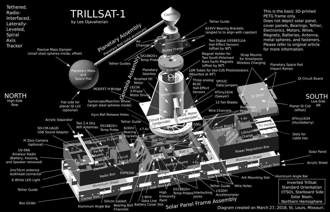
(Click diagram to enlarge)
PETG 3D-Printed Modules
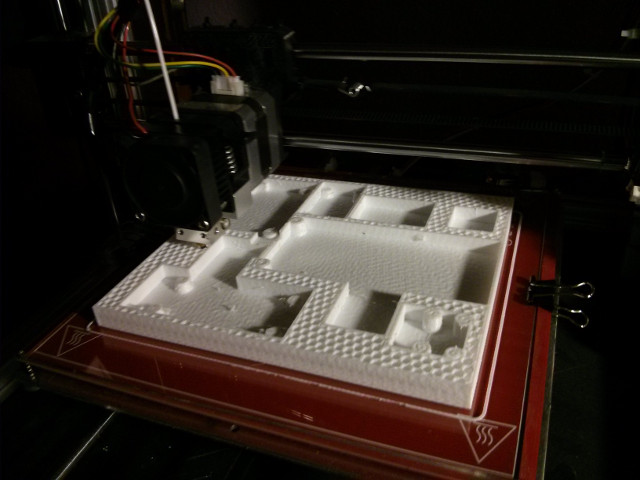
I completed most of the programming first and left the engineering until later, since I wanted to first confirm that the packet radio and XMPP system would work as I envisioned. I chose to prioritize the most difficult pieces of this project first, with the most unknowns, so that as I solved (or failed to solve) problems, I would develop more knowledge of its capabilities and could then adjust the rest of my design around these capabilities, as needed. It created a lot of excitement as I solved new problems and discovered new possibilities, but it was also demoralizing as time went on, as I had nothing to show for my work for a long time. Up until the very end, the craft was a series of solved problems, disparate pieces and modules, nothing was unified or coherent. The conscious mind needs a focal point, the mysterious "object" that I have written about before. To converge thought, to focus, naturally eliminates extraneous possibilities, simplifying the equation at hand. It's almost as if the immaterial world resolves itself, manifesting into something real, the 3Dprinter being an analogy of this process.
TRILLSAT-1: My First Prototype
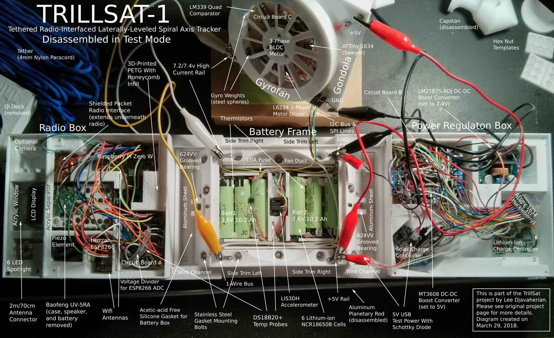
(Click diagram to enlarge)
I split the craft into five major sections:
- The Solar Panel Frame Assembly
- Two opposing Circuit Boxes
- The central Battery Frame
- The motor Gondola
- The Planetary Assembly
Excluding the Circuit Boxes, I call the mechanical/solar platform TROT (Tethered Rocking Orbiting Tracker). The Circuit Boxes essentially turn the TROT platform into a full XMPP-to-Packet radio station, but the TROT platform is a distinct robotic and power-harvesting mechanism on a single tether that could be used for a variety of other purposes.
The size of the modules was primarily dictated by the approximately 200×200 mm maximum print area of my RepRap Prusa i3 printer, which matched well with the width of the solar cells and also the diameter of the Gyrofan (coincidentally, a compact disc fits almost perfectly).
18 Unique 3D-Printed Parts
The Solar Panel Frame Assembly
The Solar Panel Frame encapsulates solar cells in a rigid, weatherproof frame which covers the entire top of the craft, all other modules hang underneath, shaded from the sun. It is a sandwich of clear acrylic on top, solar cells and temperature sensor in the middle, PETG (reinforced by aluminum angle bar) on the sides in the form of Corner Trim, Side Trim Left, Side Trim Right, two supporting Braces, and aluminum sheet metal on the bottom, acting as both a heat sink and optional RF ground. This sandwich was sealed and secured in place with acetic-acid free, clear silicone caulk around the edges which also helps to add rigidity (like a partial, crude composite laminate).
The Circuit Boxes are directly underneath, one at each end, leaving a gap for the tether and cooling airflow, and each of them contains its own smaller, custom circuit board: Circuit Board A in the Radio Box, and Circuit Board B in the Power Regulation Box. Since the enclosures hang underneath the panel, I designed the pieces so that assembly takes place with the entire unit flipped upside-down, in ITSO orientation, resting on the solar panel. This provides a stable base for me to easily assemble the modules, and the screws are easily accessible. It also provides just enough visibility and access to allow the threading of the tether through the guides and grooved bearings, but it is a bit cumbersome, requiring needle nose pliers, tape and wire. It also allows me to test the entire unit indoors, including the planetary motor, while it is upside down. It can't actually traverse a rope or tilt the panels in the inverted orientation, so I designed a wooden Ark and Test Frame for this, but I can access the USB charger and battery packs to charge them without solar power during testing, and I can monitor and check the motors and sensors. The accelerometer can even detect that the unit is inverted to allow it enter Test Mode or Demo Mode automatically.
Side Trim Left and Right
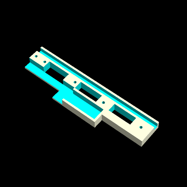

The sides of the Solar Panel Frame Assembly are reinforced by a box girder-like structure of side trim which also provide wire channels between the Circuit Boxes and Battery Frame.
Corner Trim
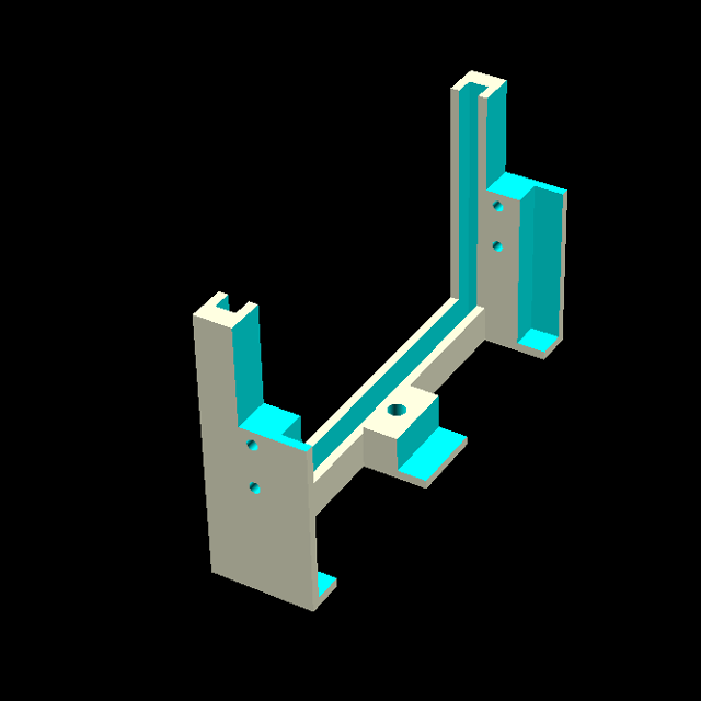
Two corner trims cap the ends of the solar panels, acrylic and aluminum sheets, provide the end tether guide holes and allow the Circuit Boxes to be mounted underneath.
Brace
Two braces add structural support to the frame assembly and also incorporate a tether guide. The open rectangular holes allow rainflow and reduce weight.
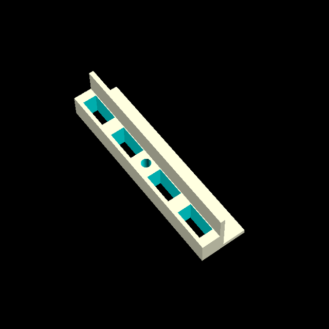
The Circuit Boxes
The Circuit Boxes contain inset boxes and screw mounts for all circuit boards, and some are even two-level mountings with circuits placed atop one-another so that I could cram in all of the circuits that I needed. For example, the UV-5RA radio is mounted atop the packet interface, Power Regulation ATtiny microcontroller is mounted atop the battery charger board, and the 5v boost converter is mounted atop the battery series relay.
All inter-module wiring is confined to the wire channels on the sides of the craft, crossing through the Battery Frame wire guides. Each Circuit Box has an aluminum cover panel which can be grounded for RF shielding. The Solar Panel Assembly heatsink can also be grounded to complete the shielding on the opposite side of the boxes.
The Radio Box
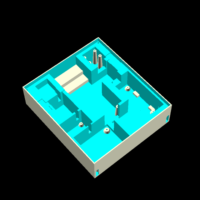
The Radio Box contains the 2 main WiFi-enabled CPUs and the amateur radio transceiver. In actual use, the craft is tilted so that the Radio Box is the higher end, nearest the tree.
The Window
All good spaceships have windows, right? This piece is not 3D printed since it had to be transparent and is a section of clear acrylic (the same type used to cover the solar panels) that acts as a window. This allows an LED Spotlight to shine down, an optional camera to take photo/video, and information on the radio's illuminated LCD display to be seen.
The Acrylic Separator
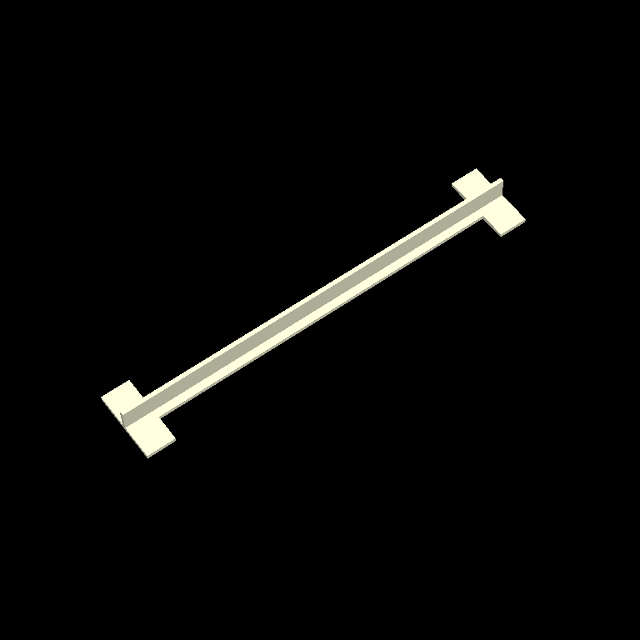
The Acrylic Separator separates the Window from the aluminum cover panel, mainly serving to prevent water from flowing underneath the panel which was too difficult to print into the Radio Box due to the underlying voids for the circuits.
The Power Regulation Box
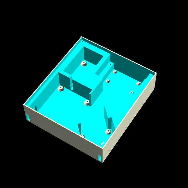
The Power Regulation Box is at the lower end, nearest the ground. I formalized this to a left/right Trillsat Standard Orientation (TSO) and Inverted Standard Orientation.
Many of the functions of the Power Regulation Box switch high and low current at various frequencies, containing its own dedicated microcontroller, boost and buck converters, different types of transistors, inductors, and DPDT relays.
CPU Holder
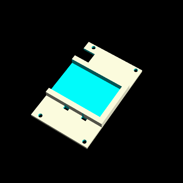
The CPU Holder is simply a small shelf that sits above the Lithium-ion charger board to mount one of the ATtiny Microcontrollers (Huckleberry). In my first design, I had two charger boards, one atop the other, but I later damaged one of the boards which forced me to come up with a better design that only used one board and incorporated the microcontroller, so I simply designed a small mount into the shelf with holes for cable ties to secure the chip in place.
Qi Dock

There is also a dock which I added later, which contains a Qi wireless charging coil and circuit board. The Qi Dock covers half of the box, protruding downward with sloping sides to allow a tight tolerance for a rotating mass with a Qi receiver (Planetary Space Pod). Logistically, this isolation of the Power Regulation Box was ideal, as it reduced the wiring needed, but it also had the benefit of distancing (inverse-square law) any stray RF caused by the regulated power switching that could interfere with the audio or radio modulation.
The Battery Frame
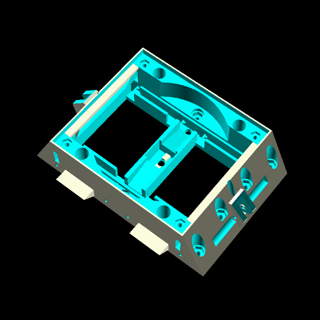
The central Battery Frame is in the center, the nexus, or bottleneck, between the two Circuit Boxes, and is the most complex single part, structurally rigid with high compressive and tensile strength, bolted to the aluminum lower panel of the Solar Panel Frame as it has to withstand rather large mechanical forces. It contains wire channels and slots for the Battery Cover.
Two Battery Boxes
When bolted to the aluminum, the Battery Frame forms two small boxes, which I call the Battery Boxes, which house two energy-dense Lithium-ion battery packs (3 parallel cells each). In between the two boxes is a 3-axis accelerometer (which contains its own temperature sensor) and a separate temperature sensor in-between the solar panels, which sits at the center of the 3 axes. It contains two 624vv grooved ball-bearings, acting as pulleys, and four custom, stainless steel, high-current electrical terminals that are exposed externally and are electrically isolated from the solar panel, secured in place. The cells are temperature-monitored and temperature-regulated by using all 3 heat transfer methods (radiation/emmissivity, conduction, and convection), being protected by an aluminum shield which can be grounded and is held in place by a lower Gondola.
Battery Cover
A cut and bent piece of aluminum sheeting acts as a Battery Cover, turning the Solar Panel Assembly and Battery Frame into true Battery Boxes. This cover protects the batteries and accelerometer from the spinning Gyrofan and is held in place by the Gondola and upward forces of the tether. If the Battery Boxes overheat in the summer, the cover acts as a heat sink, in conjunction with the Gyrofan. The underside of the Battery Cover is covered with insulating tape to prevent short-circuits as it pushes up against the battery wiring.
Fan Duct
When the Gondola is assembled to the Battery Frame, it forms an active fan duct for the batteries, as the Battery Frame includes just enough space to allow the Gyro to fit inside. At the time of this writing, there are few ventilation shafts outside of the Gondola, which will eventually need to be added for effective ventilation.
The Gondola
The Gondola is the distinct, pyramidal, protruding carriage underneath the assembly that also contains it's own custom, dedicated microcontroller and Circuit Board C, along with the fan motor, which also serves as a Gyrofan, the H-Bridge and drive motor, various sensors, and pulleys. It is a "gondola" in the sense of a combination of a zeppelin gondola and gondola lift, which have different definitions, but it really isn't either of them, since it carries an on-board capstan winch, the gem-like zenith of the pyramidal assembly. The Gondola, from top to bottom in TSO orientation, is a sandwich of the Gyrofan, Motor Housing, Sensor Endcap, and Pulley Frame, in that order. The Gondola can be easily removed to open the Battery Boxes and test the Gyrofan.
Gyrofan
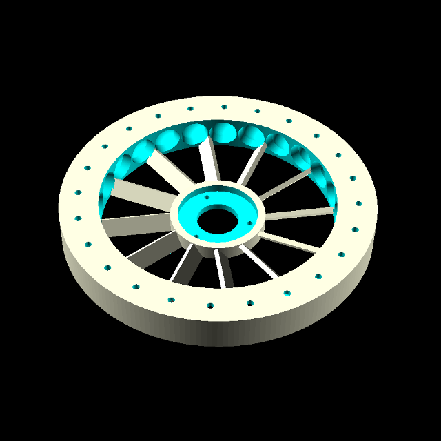
The Gyrofan is a gyroscope wheel with 12 pitched spokes that act as fan blades at high rpms. It contains 24 spherical cavities around the outer edge to house heavy steel balls to provide gyroscopic momentum, along with tiny ejection holes, through which a pin can be inserted to pop the balls out of the cavities during adjustment/calibration. The Gyrofan can only be tested easily when the Gondola is removed, using jumper wires to maintain the electrical connection, since it is invisible once inside the Fan Duct. This is experimental.
Motor Housing
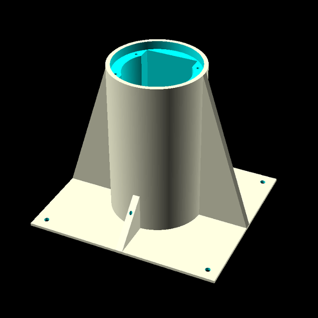
The Motor Housing is the large, finned section of the Gondola which supports the Gyrofan BLDC motor and Circuit Board C, but also houses the screwdriver drive motor and planetary gearbox.
Magnet Holder

Inside the Motor Housing, attached to the screwdriver shaft, is the Magnet Holder which supports two rare-earth magnets, offset by 90 degrees. The holder was necessary to ensure correct angles of the magnets, as manual placing is difficult, aiding in adjustment/alignment with the Hall-effect sensors.
LDR Tubes

Attached to the 45-degree side fins of the Motor Housing are two LDR Tubes which house CdS Photoresistors (commonly called LDRs, Light Dependent Resistors). There are holes in the tubes and in the Motor Housing fins for the LDR wires. The Tubes are covered with thin, clear PET plastic that I cut from of an old blueberry produce container to prevent rain from entering. The tubes need to be lined with opaque inner-tubes to prevent sideways light leakage through the translucent white PETG which can skew the readings.
Endcap
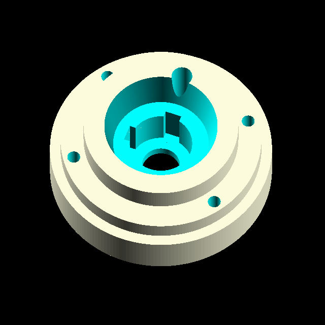
The end of the Motor Housing is capped with the Endcap, which insets into the housing to mechanically secure the top of the screwdriver and align two digital Hall-effect sensors (also offset by 90 degrees) just outside the diameter of the Magnet Holder. It also includes an external shaft for a DS18B20+ temperature probe, designed to allow outside air to quickly convect and conduct through the shaft for external air temperature sensing.
Pulley Frame
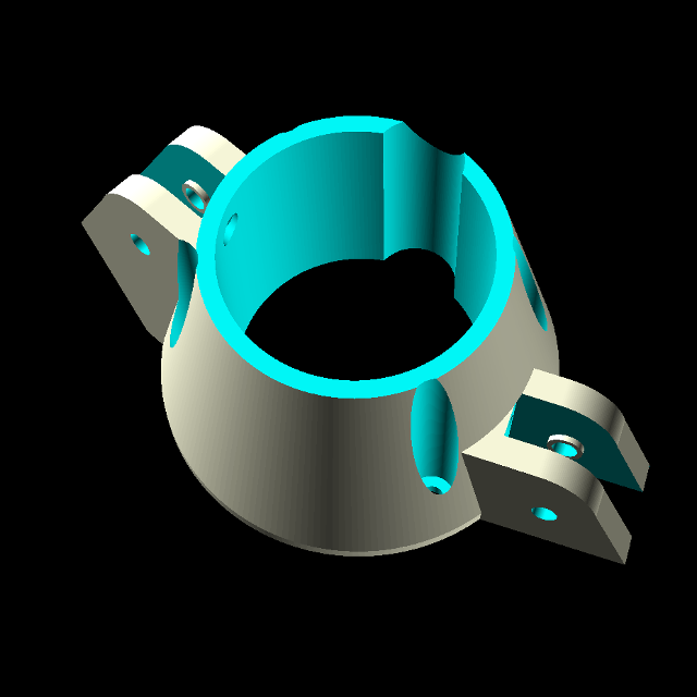
The Pulley Frame is mounted to the Endcap and also contains two 624vv ball-bearing pulleys. The taut tether applies upward force to the pulleys which helps to keep the Pulley Frame, Endcap, Gondola and Planetary Assembly firmly in place.
The Planetary Assembly
The Planetary assembly fits inside the pulley frame to the steel, hexagonal shaft from the drive motor, and the entire, heavy assembly is held in place by the force of the tether, which is quite strong. So the Capstan is strong enough to withstand these forces as well as also supporting and connecting an aluminum Planetary Rod to the orbiting Planetary Mass or Space Pod.
Capstan

The Capstan is the powerhouse of the entire craft--it is like the Sun at the center of our solar system, the source of power for propulsion and orbit of the Planetary Mass, requiring a careful shape to achieved effective operation. I've been experimenting with a variation of this shape in my newer Camstan.
Planetary Rod
The Planetary Rod was not 3D-printed due to strength/weight limitations and is a solid aluminum rod that connects the orbiting mass to the Capstan. Its angle and length are critical, which are not adjustable and are printed into the Capstan and Planetary Mass. Since the Planetary Mass is heavy, the rod tends to bend and shift the drive motor shaft off-axis, so the rod hole in the Mass had to be offset to compensate for this unexpected difference. Slots had to be hacksawed into the ends of the rod to allow epoxy to form a mechanical bond with the PETG plastic (also slotted) to prevent the rod from rotating (since PETG is impervious to most glues).
The Planetary Mass or Space Pod

The Planetary Mass is the rotating mass, a hollow sphere, with an interior geometry, filled with steel balls acting as both a single, weighted mass and a ball mass damper, connected to the Capstan, that orbits the central drive motor axis. I also call it the Planetary Space Pod, since it has flattened side to allow tight tolerance for a planar, Qi receiver coil and ESP32 LoRa board (something I may add in the future) which can orbit around and dock at the Qi Dock, but at the time of this writing, it is only a placeholder and mainly serves as a mass to tilt the attitude of the craft. When I think of it as a self-contained machine, I usually call it the pod, but when I think of it as a weight, I usually call it the mass.
Three Circuit Boards
Three main circuit boards were mostly constructed using dead-bug style techniques which allowed for better density, easier electronics troubleshooting (since everything is on the topside) and reduced the height of the wiring underneath the board.
Circuit Board A
This is the simplest of the 3 boards, and allows the Pi and ESP to control the Radio and Pi power supplies directly. It also provides the reset circuity for the ATtinys and the basic driver circuitry for the LED light and the 1-wire temp sensor network. The smaller jumpers are for data signals and low-current sensing, and the larger, blue terminals are for higher-current power transmission.
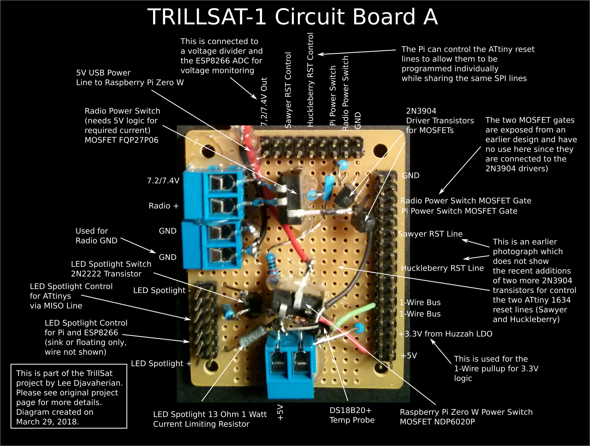
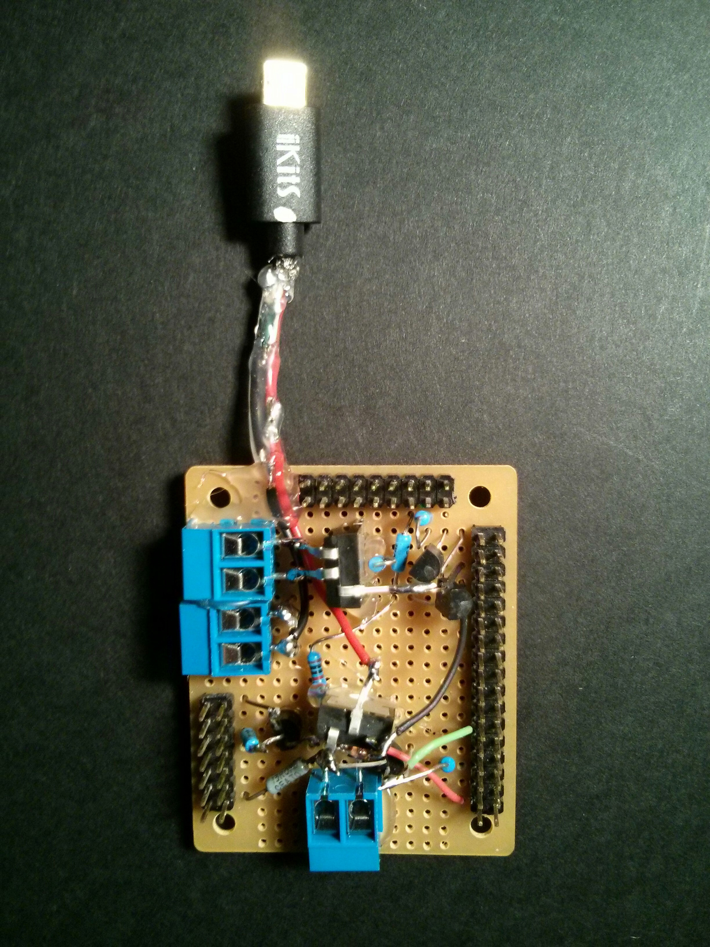
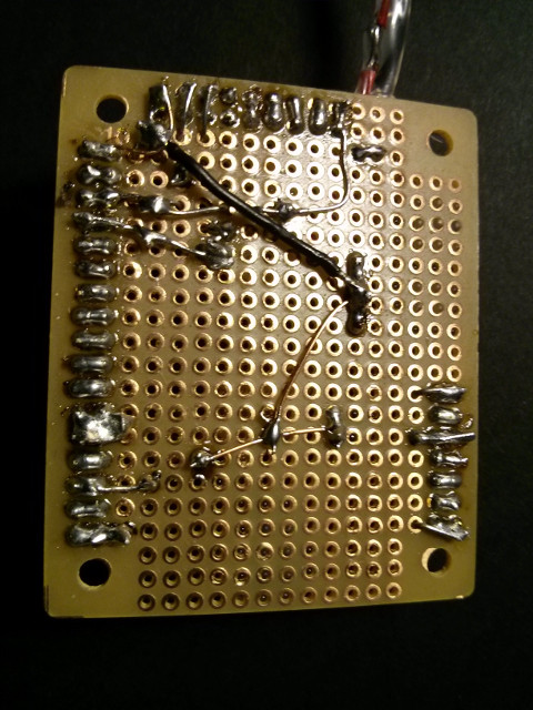
Circuit Board B
This is the most complex and dense board of the three, containing 8 bipolar junction transistors and 6 MOSFETs, providing all of the power switching for the craft, but I also crammed in 2 electromechanical DPDT relays (one momentary, and one latching) for situations the MOSFETs don't handle well, a 5 volt DC-DC boost converter, and a bootstrap power switch. The bootstrap power switch in the upper left is useful if there is no solar power present, since it turns on a MOSFET which allow the system to boot-up and then keep itself on. It was originally designed to be controlled by the Pi GPIO but this duty has since been moved to an ATtiny microcontroller (Huckleberry) which connects to its original jumper pins. As with Circuit Board A, the smaller jumpers are for data signals and low-current sensing, and the larger, blue terminals are for higher-current power transmission. I had to re-build this board from scratch a second time before I got it right, since I used through-hole assembly on the first attempt which was a nightmare to troubleshoot and modify, and I simply ran out of space.
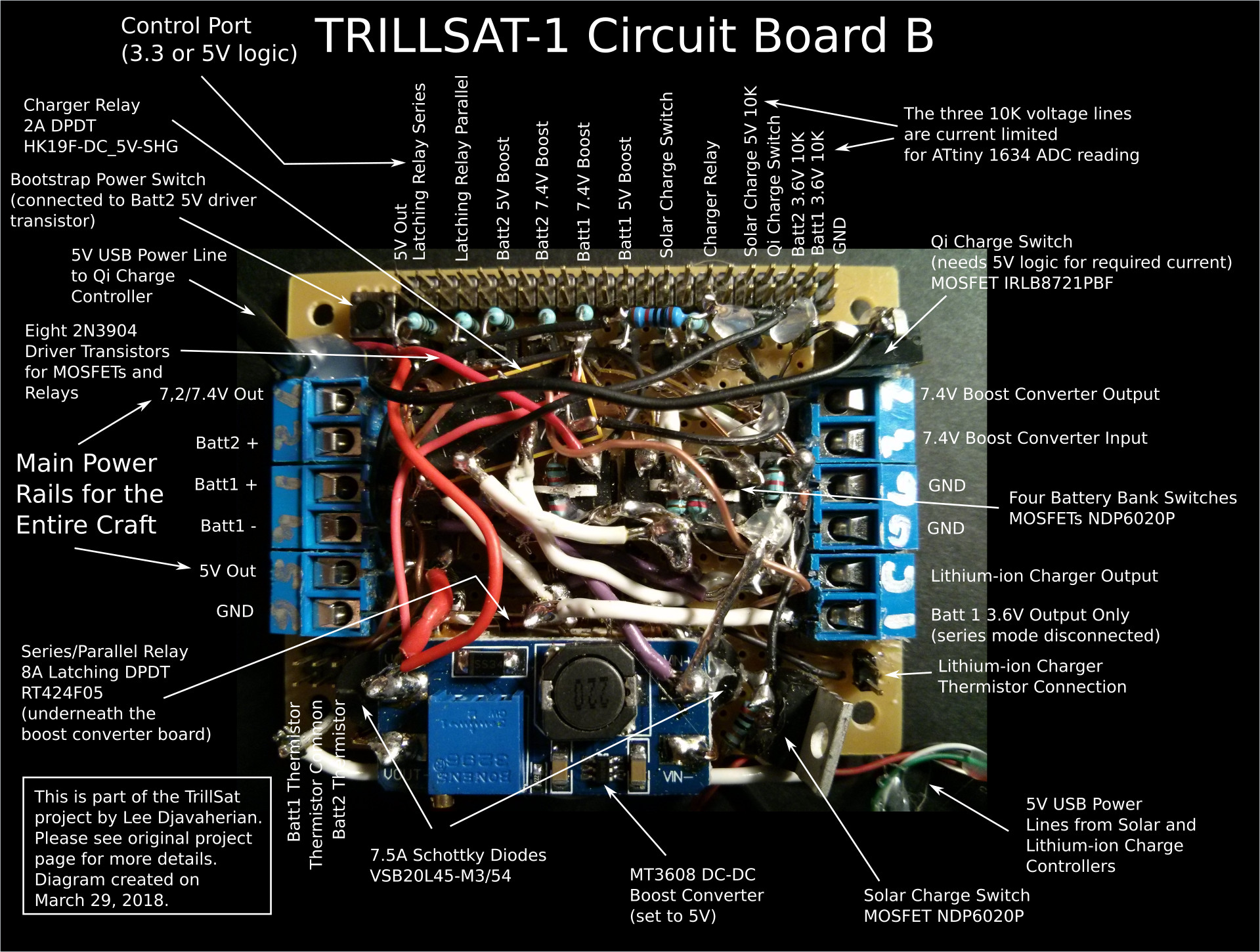
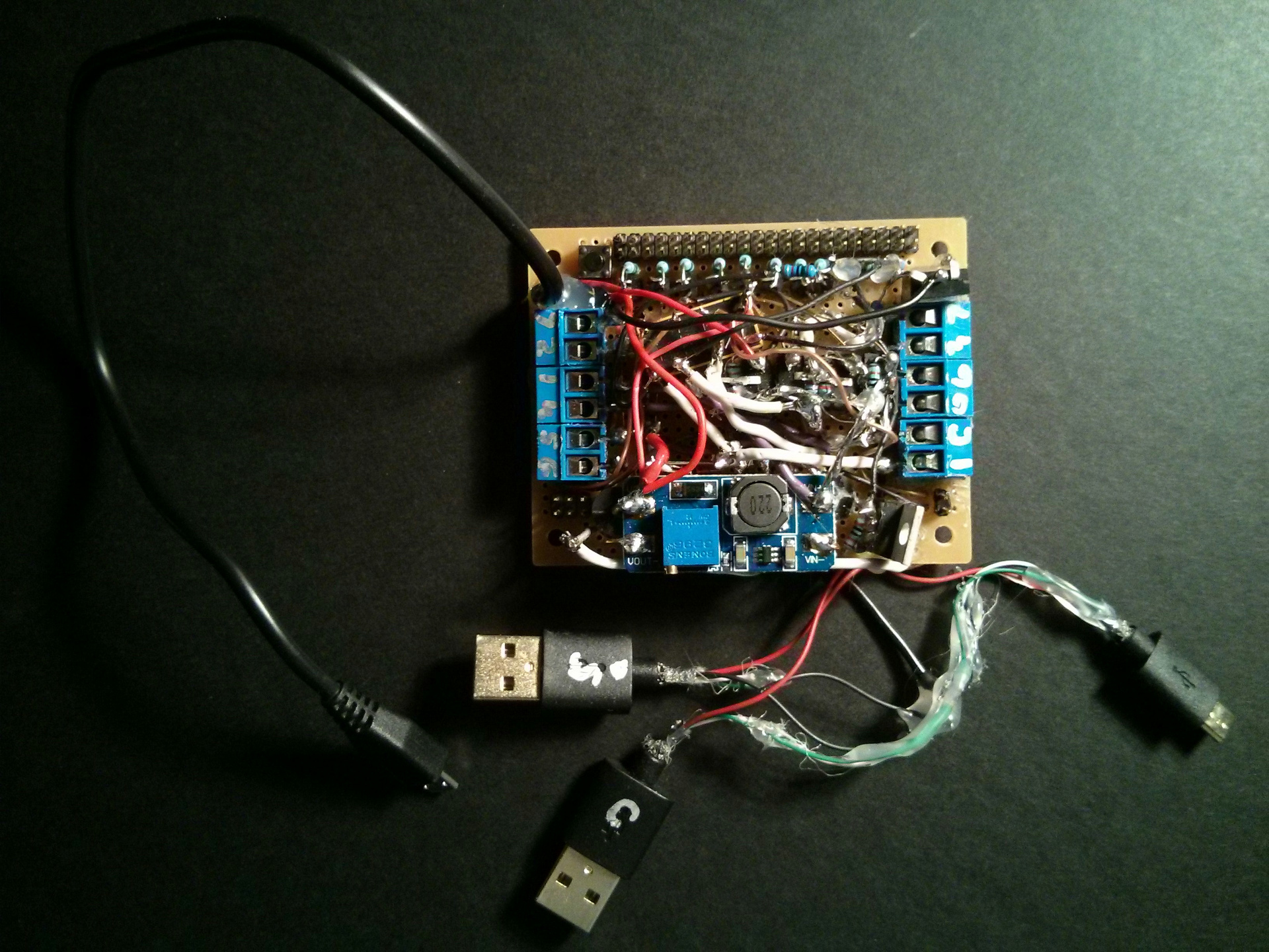
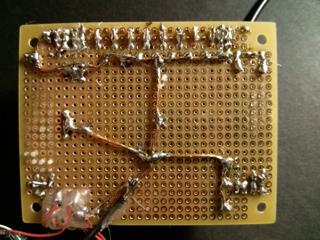
Circuit Board C
This circuit is hot-glued to the PETG blackplane, with barely enough clearance underneath the spinning Gyrofan. It contains its own ATtiny microcontroller (Sawyer), an L6234 3-phase motor driver chip, along with a quad comparator, to control the central BLDC motor with its 3 analog Hall-effect sensors. It also provides the CdS LDR sensor outputs. The higher-current power transmission is connected to 3 of the 4 end terminals at the corners, the rest of the terminals are for data/sensor signals. I had to rip out my first ATtiny when I wired it upside-down, so the wiring became a mess once I soldered in a new ATtiny and the wires were then reversed. I also burned out the BLDC during a rare cascade failure which locked up the ATtinys and stalled the motor but have since replaced it and turned on brown-out detection.
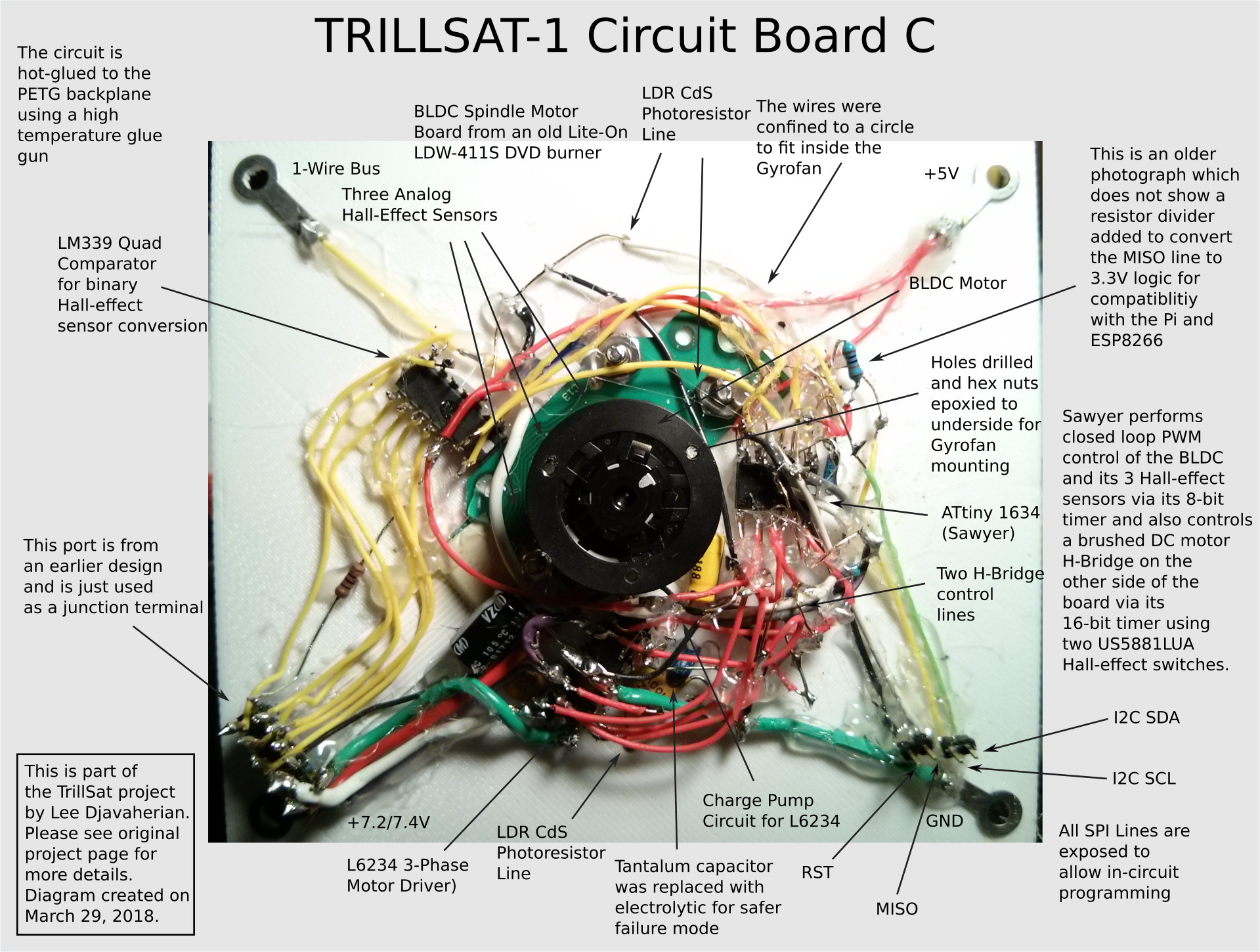
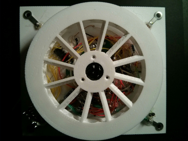
There are also several specialized circuits that I built into different assemblies such as the radio interface (underneath the UV-5RA radio), the H-bridge (inside the screwdriver housing), the module and mount for the ATtiny (Huckleberry), and the Endcap which contains various sensors.
The Full Schematic
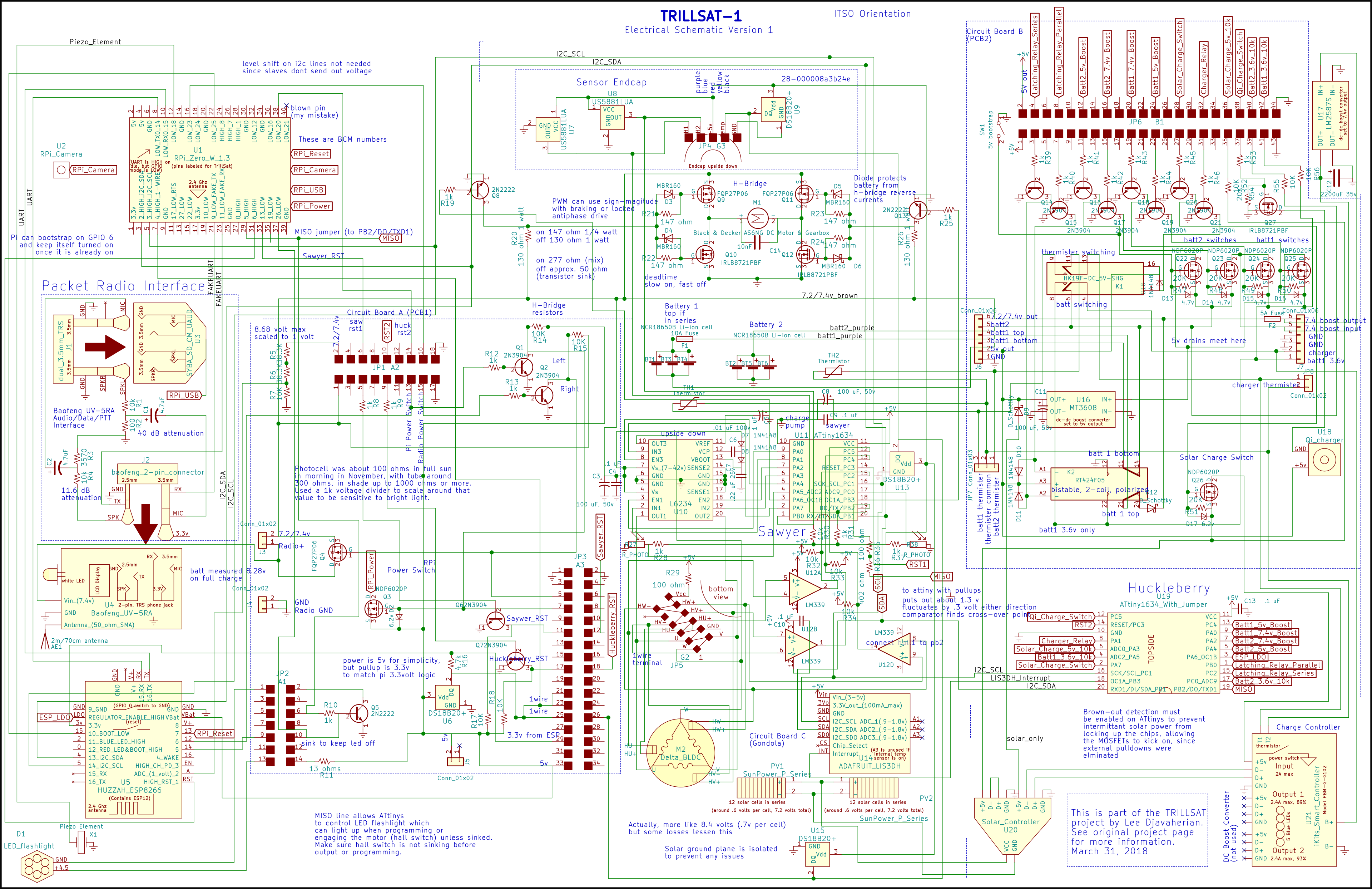
(Click diagram to enlarge)
MOSFET Insanity
In my earlier PacketRadio project, I designed it for use with a single, simple SPST relay, but for this project, I decided to primarily use MOSFETs, and I ended up using a lot of them. Besides a few resistors for the sensors, almost all of my circuit design involves switching circuitry, switching modules on and off to perform various functions. So I immediately knew that I would need a lot of transistors. I have a long history of using BJT (bipolar junction transistors) in conjunction with electromechanical relays, but I wanted to use some of the modern power MOSFETs (a type of Field Effect Transistor) to keep the current use low and reduce mechanical failure. I had read about FETs decades earlier thanks to the wonderful books by Forrest M. Mims III, but had never actually used one before. I have some experience with optoisolators, but they are more expensive than simple BJTs and thought they were overkill in this case.
If you're not familiar with transistors for switching operations, one of the most basic concepts that differentiates them from other types of switches is that they only turn fully on or off in certain arrangements, with certain voltage differentials present on the pins. You can orient a relay, for example, any way you want and just turn the current on or off to switch the circuit with a low resistance path, and then it defaults to its off state when de-energized, but for transistors, you have to be very careful selecting the correct BJT or MOSFET with various polarities and voltages, while keeping aware of their default states. Low-side switching, which I have historically done (turning a simple device on or off by controlling the ground connection), is efficient with NPN transistors and N-channel MOSFETs, but when you want to switch one of several power lines with a common ground between them, things get tricky. MOSFETs like rather high voltages, higher than typical logic voltages, and even BJT transistors are finicky. An NPN transistor, for example, whose Emitter isn't grounded is an Emitter-follower, and acts like a different beast, limited to the Base voltage, and an N-channel MOSFET that tries to switch a power line can't fully turn on since it is very difficult to get the Source voltage sufficiently lower than the Gate. A P-channel MOSFET will turn on when you ground the Gate, as long as the ground level is sufficiently lower than the Source, but you can't turn if off again until the Gate voltage is at least as high as the Source.
This presents all kinds of peculiar arrangements that don't work, or work poorly, or work but the logic is reversed, or they drain power in their off or default states, etc. The potential pitfalls are numerous, and I hit just about every one of them (redoing a lot of my work) until I finally analyzed each use case individually.
Logic-level MOSFETs are wonderful inventions, available to turn on using lower voltages, but they are not as common in the larger TO-220 package that I wanted to use (I didn't want to do any surface-mount soldering), but many of them still won't fully turn on (or off) at the low 3.3-volt logic of the Pi Zero/ESP8266, which adds heat and decreases their efficiency, so adding a driver BJT (I chose the 2N3904) allowed me to pass higher MOSFET gate voltages. In my case, I have a unique advantage: since I have both 5v and 7.4v available via two DC-DC boost converter boards, I can leverage them to raise or lower the gate voltages to get a large enough differential for those MOSFETs to create a low channel resistance. However, there are subtle trade-offs between N-channel, P-channel, and very low VGS/RDSon voltages depending on the situation.
Logic-level power MOSFETs are several times more expensive than a common BJT, and I made the mistake of immediately purchasing ten N-channel IRLB8721 MOSFETs before I finalized my design. I had read that N-channel MOSFETs are generally cheaper and more efficient than P-channel, and I was hoping to drive them directly from 3.3v logic. But then I realized that in every case except for half of my motor H-Bridge and the Qi wireless docking, I needed to perform high-side switching, and needed ALL P-channel MOSFETs. And even if I did have a clear-cut case for low-side switching, the channel resistance was still too high to be efficient at 3.3v, draining precious power and lowering the voltage. In many cases, the 3.6v Lithium-ion voltage was just barely high enough to perform a needed function, but then the high MOSFET channel resistance stomped it down too low to be usable... I even tried doing high-side switching on the N-channel using a 7.4 volt boost converter to raise the Gate voltage, but the resistance was still too high, since 7.4 - 3.3 = 4.1. A 4.1 volt differential for the IRLB8721 was just barely too low for my needs.
Dang.
So I started throwing in more P-channel MOSFETs. I first chose an FQP27P06, more expensive than the IRLB8721, and it worked nicely with my motor H-Bridge, in conjunction with the IRLB8721. The gate capacitance is low enough to allow the relatively slow PWM frequencies that I need. My 7.2-volt (two NCR18650B cells in series) motor voltage was a wide-enough differential and the channel resistance was nice and low. The FQP27P06 is also a good match for switching the Baofeng radio on and off, simple 7.4-volt high-side switching that defaulted to an off state.
Other than my motors, one would think that there would be at least one device that I could low-side switch, but the problem is that almost all of those devices that I needed to switch have multiple I/O or power lines coming out them; they are not simple on/off devices like a light bulb. And because they all share common ground, I can't just ground the device to turn it on, as there is a spider web of current leakage through those connections that will branch out and find other routes to ground. This meant that I could only use 3 of my 10 N-channel IRLB8721 MOSFETs, which felt like a waste of some really nice transistors. The Qi charging board was a self-contained unit, so I was able to connect the IRLB8721 directly, without even requiring driver transistor.
But I couldn't just rely on the FQP27P06, since sometimes I didn't have the 7.4 volts at my disposal, so I needed a more sensitive and even more expensive P-channel that would turn fully on at lower voltages, the NDP6020P... but it had a surprisingly low max gate voltage of 8 volts... this works okay for 5 volts, but I didn't want to use it with the 7.4 volts I needed in other areas. Just a small transient increase from the 7.4v boost converter would damage the MOSFET, and cramming in a zener in that voltage range for over-voltage protection (along with its tolerance error) doesn't have much wiggle room without causing an overlap. So I used the cheaper FPQ27P06 to switch 7.2/7.4 volt circuits, such as half of the H-Bridge and the 7.4 volt line to the UV-5RA radio, but then used the NDP6020P to switch the 3.6v supply inputs to the boost converters, the 5 volt outputs from the solar panel, and the 5v supply line to the Pi Zero, adding 4.7 and 6.2 volt zener diodes, depending on source, to protect the gate from high transient voltages.
Originally I designed my board for the 3.3 volt logic of the ESP and Pi Zero, but then when I added two ATtiny1634s later, I used 5 volt logic, eliminating the need for the gate driver BJTs on the NDP6020Ps (but then I also had to perform a bit of level-shifting). I didn't put gate pulldowns on the board either, as I was going to use the Pi Zero pulldowns... Well luckily, the 5v logic increases the base current across the series resistors, which I needed to increase the current capacity of the 2N3904. These types of BJTs are dynamic and vary their gain depending on the voltages and currents used, and the gain usually drops off near the max current, requiring higher base current. This raise to 5 volt logic also allowed me to drive an IRLB8721 directly from the I/O pin, which was the best arrangement for an N-Channel MOSFET, as a gate driver BJT reverses the logic and draws power to keep the MOSFETs off.
The 2-amp MT3608 step-up converter chip that I used to generate 5 volts has a minimum 2-volt input voltage, but the 5-amp LM2587-ADJ that I used to generate 7.4 volts is higher at around 3-4 volts. Since the nominal voltage of the Lithium-ion batteries that I am using is 3.6 volts, this doesn't provide any leeway for providing supply to the converters. So I had to be careful to avoid any voltage drops from diodes (I didn't even use a Schottky) and had to keep the MOSFET channel resistance low.
In the end, there was no simple MOSFET solution to turn on a 3.6 volt input to get a high-amperage 7.4 volt output. With the FQP27P06 P-channel MOSFETs, I couldn't leverage the 7.4 volts to increase the differential (since I can't feed the 7.4 volt output back into its input) and it remained at 3.6 volts. If use an N-Channel, I can feed the 7.4 volts back into the Gate to get that differential, but again, with high-side switching, the Source remains elevated and this removes some of the gains of the higher gate voltage... So both boost converters are limited by the NDP6020P channel resistance at 3.6 volt Gate-to-Source differential which is luckily high-enough for that logic-level MOSFET.
Building a high-current H-Bridge for PWM modulation was also much more difficult that I expected (which I explain later in the H-Bridge section) and I also needed to use capacitors for voltage/current protection and had to add "deadtime" to prevent a short circuit shoot-through condition.
Something else surprised me: I had to replace some of my MOSFETs with a relay, since I needed as close to zero resistance as possible to avoid interfering with the battery charging boards or the ground plane. The old electromechanical relay still has the advantage here since MOSFETs have a higher channel resistance. The relays drew more current but were still within the range of the 2N3904.
Since just building one simple 4-MOSFET H-Bridge was so difficult, I decided not to use discrete MOSFETs for the 3-phase BLDC gyro motor, as I would need a whopping 6 of them just to drive 1 motor, and used a 5-amp L6234 driver IC for the BLDC (which contains 6 internal MOSFETs) which was simpler, smaller, and slightly cheaper than buying them separately, able to run on a 7 volt or greater supply voltage. I didn't like doing this, but I didn't have much room and it also wasn't worth the additional cost or complexity to build the 3-phase driver completely from scratch for an "experimental" BLDC gyro. BLDC motors are mechanically simple, but I found out the hard way that they are extremely difficult to drive and commutate, which I explain later in the gyroscope section.
Finally, I did have a brief delusion of grandeur where I attempted to scrap the 7.4 volt boost converter completely and just build my own Dickson charge pump voltage doubler from scratch using those same MOSFETs ...but then I read more about it and realized that it would be hugely inefficient for the current levels I needed. The concept is fascinating, though.
Transient Over-Voltage Protection
As mentioned earlier, I added 4.7 and 6.2 volt zener diodes between the Gate and Source on the NDP6020P P-Channel MOSFETs to keep the Gate-to-Source voltage differential as low as possible, away from its 8v maximum. The 4.7 volt zeners allow for max voltages of the Lithium-ion cell, and the 6.2 volt zeners allow for max 5+ volt USB voltages. These are not TVS diodes and are probably not fast enough to equalize really fast transient spikes, but at least the 6.2 volt zeners might prevent me from accidentally tweaking the 5v boost potentiometer past 8 volts and blowing those MOSFETs. (I did have a few encounters with static electricity while working on the circuitry in the dry winter air, but luckily it didn't cause any noticeable damage.) Even the Lithium-ion batteries in series, when fully charged, exceed the nominal 7.2/7.4 volts and can reach 8.4 volts... I didn't use diodes on the FQP27P06 or IRLB8721 MOSFETs, since they have max Gate-to-Source voltages of 25 and 20 volts, respectively, but I am taking a risk.
Qi Wireless Docking at the Space Port
The Power Regulation Box at the lower end of the craft contains a planar, inductive Qi coil and wireless charging circuit that can be switched on or off allowing wireless electrical power transmission without physical contact. This is the Qi Dock, or "space port", so to speak, that allows the temporary charging of a Qi-capable smartphone and allows an orbiting "space pod" to dock for charging, using the accelerometer for guidance (since it is on the "night" side where the Hall-effect sensors are not present). The dock coincidentally looks somewhat like a sci-fi shuttlecraft and almost perfectly matches the size of my Nexus 4 smartphone, with a coil, offset slightly from center, to line up with the phone. It activates within about 5 mm from the dock (as long as its control MOSFET is turned on), a fairly tight tolerance, and the side "pontoons" are actually rounded hooks for rubber bands or hook-and-loop straps to temporarily secure the phone.
There are side ramps on the dock that allow the mass to get very close to it (within the range of the wireless induction) allowing potential side impacts to skim across it. It is aligned so closely so the mass can one day be replaced by the Planetary Space Pod. The dock is offset lower than the rest of the craft, since the Planetary Mass/Space Pod skims so close that it might accidentally impact the other side of the craft, the Radio Box, on its orbit since there is not as much downward force on the planetary rod at that higher angle. The Planetary Mass/Space Pod is also aligned so that its orbit perfectly crosses the coil, even though the coil is offset and not centered, since it is still a valid point along the circle.
The docking Planetary Space Pod is a future experiment to someday house a Qi receiver, ESP32 LoRa board, and Lithium-ion battery to create an autonomous pod that is not fully under the control of the main craft and has no direct electrical connection with it, allowing it to partially control its own orbit under its own discretion, monitor its own power, like a real space extravehicular activity. Miles away, a remote user could contact the tiny pod hanging high in the air via its LoRa radio, so it provides a nice way to test the new, inexpensive LoRa technology.
I haven't placed any electronics inside the Planetary Mass to turn it into the Space Pod yet, but have only filled its specially-shaped interior with small steel BBs to provide weight and ball damping (like the metal balls inside a dead blow hammer, for example).
Smartphone Charging
At this time, the wireless docking mentioned above is only for charging a Qi-capable smartphone, with solar power stored in the craft's batteries along with real-time solar power, an important function of the craft when power is not available, as the smartphone is the primary client interface, perhaps the only interface available in a power outage. Since the Qi charger requires around 2 amps of current, which maxes out the 5v MT3608 boost converter, it is necessary to only to dock in the daytime when excess solar power is available (via a Schottky diode) and/or shut down the radios and higher CPUs to allow higher current availability.
The absence of external electrical charging ports keeps rain and moisture outside of the craft's housing and makes charging easier. The charging LED can be seen changing color through the translucent PETG at the back of the dock, based on its charge status, although the charge status can also be determined by the phone's display screen. The dock was designed around the dimensions of my Nexus 4 smartphone, one of the first phones to support built-in Qi charging. But today, low-cost receiver adapters can be purchased, and receiver adapters can also be added to non Qi phones.
The craft is lowered to standing height and parked at solar noon position, which allows a person to use hook-and-loop straps or rubber bands to easily secure the phone to the dock without interference from the large Planetary Mass. The front-facing camera on the Nexus 4 could, in theory, record video while mounted to the dock, and the craft could perform full tilts changing the view without impacting the phone (as long as it confines itself to a half-orbit), but since the craft can carry an optional Raspberry Pi Zero camera which is lighter and more versatile, this is not advantageous.
Four CPUs
For failsafe redundancy, power management, and reducing the large number of data wires that span the modular design, I incorporated 4 CPUs. There are additional custom CPUs on various boards, but I added these 4 for my own custom programming. In order from largest to smallest, there is a RaspberryPi Zero W (programmed in Python 2/3 and BASH), an ESP8266 (programmed in Lua via NodeMCU) and 2 ATtiny 1634s (programmed in C via AVR-GCC, AVR Libc, and Avrdude). The Pi and ESP are in the CPU and Radio box, one ATtiny is on the Gondola, and the other ATtiny is in the Power Regulation box.
The Pi and Linux OS is required for handling the complex AX.25 packet protocol and software AFSK modulation, which would be difficult to implement on the ESP8266, which lacks an AX.25 stack. Linux has had kernel support for AX.25 for a long time. But the ESP is a very reliable and power-efficient WiFi microcontroller, so I used it for XMPP communication, although I did have to program a custom XMPP server on the unit, as I knew of no such software in existence using Lua (most of it is MQTT instead), but that is still much easier than AX.25. The ATtinys were added for low-level sensing and control over most of the craft's motor and power subsystems. In fact, other than the higher-level algorithms and radio functions, the two ATtinys can control the entire craft and TROT mechanism themselves, working independently on their own subsystems, which is only unified when you look at what they are doing from a higher context. Combined with the haptic protocol, full communication with the craft would still be possible even if the Pi, ESP, and smartphone were down.
Managing communication between the various CPUs was tricky. The Pi and ESP both have nice I2C interfaces (a bus-based communication protocol that only requires 2 wires) but they are designed as "masters" in the original software implementations. The ATtinys are slave-only at the hardware level and cannot be configured as master. I used the UART serial line (a point-to-point communication protocol that only requires 2 wires) between the Pi and ESP, but this complicated the issue communicating with the Baofeng UV-5RA (which also requires the UART). So I had to use a software UART to communicate with the radio. Currently the Pi Zero W is acting as the single I2C master for purposes of communicating with the ATtiny slaves and the LIS3DH accelerometer (also an I2C slave), and it receives control messages over the UART from the ESP's WiFi XMPP server. This was the easiest arrangement to get most of the functions working, as the Pi can easily handle the floating point trigonometric tilt angle calculations without worrying about running out of memory. But in the future, I plan to program the I2C master commands on the ESP as well, so that it can also control the ATtinys directly after the Pi is shutdown.
The ATtinys contain a huge number of features for their cost (under $2 in the US) and size. I was already familiar with programming them, since I used them on my TinyRoomTinyWorld solar-powered game, and it wasn't very difficult to adapt them to this project. Excluding power, they only require 4 IO lines from the Pi Zero for SPI in-circuit programming via Avrdude (and these can be any lines, since it can use software bit-bang programming). Two of the lines are already used by I2C and are connected full-time, so I only had to run 2 additional wires to allow permanent in-circuit programming, the MOSI and their individual reset (RST) lines (so that I could select which chip to program) by using different avrdude.conf file pin settings for each chip.
Note that during the two-year span between early 2016 and early 2018 when I was programming and building TRILLSAT-1, there were several inexpensive microcontroller advancements that occurred which caught me by surprise:
- ESP32 (late 2016)
- Raspberry Pi Zero W (early 2017)
- ATtiny 1616 (early 2017)
- Inexpensive ESP32 LoRa radio boards (late 2017)
The ESP32 is more expensive and power-hungry (dual-core) than the ESP8266, so it is not a substitute for its function, but the ESP32 LoRa boards are perfect for my Planetary Space Pod experiment, increasing its range, which I had previously envisioned for an ESP8266. The Pi Zero W was slightly more expensive than the Pi Zero, but it gives me a separate WiFi card which made programming it easier and leaves a USB port open for the sound adapter, so decided to replace the Pi Zero with a Pi Zero W. The Pi Zero W WiFi doesn't make the ESP8266 WiFi obsolete, as the ESP8266 uses less power overall and has good WiFi range, so they are a good complement to each other, and I created XMPP commands on the ESP8266 that allow me to disable/re-enable the Pi Zero W WiFi adapter, or even the Pi itself, to save power.
The ATtiny 1616 is more powerful and less expensive than the 1634s that I am using (under $1 in the US), created after Microchip acquired Atmel. But I already had several 1634s on hand and the software tool chain hadn't caught up with the 1616s yet. The 1616 has double the RAM, has master hardware I2C capabilities, more timers, and single pin programming, things I could have taken advantage of, and it will be my chip of choice in the future. But I had an adventure trying to push the limits of the older ATtiny 1634s to the max.
Benefits of Combining the ESP8266 and Pi Zero W
The ESP8266 is an amazing device for the price, is widely available and could be found priced below the Pi Zero W, under $5. I decided to use a slightly more expensive version for my first experience with the chip, the Adafruit Huzzah ESP8266 Breakout board which I was able to find for $9.95. The Internet of Things (IoT) community has helped to provide information and tools about this chip, and it reminds me of the energy you see in the Arduino or Raspberry Pi groups. It is a Chinese-made microcontroller with WiFi capabilities, and was originally designed to allow programmers of small micro-controllers to attach the chip to their UART serial port and send AT-style commands to it to act like a TCP/IP WiFi modem. It was not designed to be connected to high-powered ARM processors like the Raspberry Pi and therefore has low throughput compared to a USB WiFi card.
However, I decided to connect this device to the Pi Zero W's UART and use the ESP8266 as the sole TCP/IP networking device, programming an XMPP server directly on the ESP, allowing it to receive messages and commands and power down the Pi Zero W's internal WiFi card. Few people have connected these two devices for such a use, but it has several benefits:
- The ESP8266 is the primary low-power communication and control CPU of the system and can even control a few GPIO lines. This turns the project into a two-master system, allowing me to shut down the other computer to save power, turn off WiFi radios, or perform maintenance on the other unit, while still maintaining relatively high-level functions. The Pi Zero W, for example, has no off switch, but I added MOSFET power control to allow both the ESP and Pi to do this (the Pi breaks its own bootstrap cycle). And both CPUs can control the two ATtiny microcontrollers, which are in charge of the low-level functions, over the I2C lines.
- The Pi Zero W is the powerhouse of the system and can perform all of the AX.25 packet radio communication, sound modulation, and floating point calculations without worrying about memory constraints. It uses a multitasking Linux OS allowing high-level interaction with the Unix subsystem, BASH, and Python. It provides nice programming tools for the rest of the devices.
- The ESP8266 can be reprogrammed on-the-fly by the Pi Zero W if needed (which is actually how I programmed it to begin with) which can overcome memory limitations in the device if additional functionality is needed at certain times.
- The Pi Zero W has no traditional sleep modes and cannot sleep to save power. Even if a USB WiFi card was connected, the Pi Zero W itself would have to remain awake. The ESP8266 can be put into several sleep modes, using DTIM, with WiFi on, or it can go into a mode where the entire chip is powered down and it can be awoken from one of the low-power ATtiny microcontrollers that run the craft's low-level subsystems. This allows the entire system to power down in stages, drawing very low current.
- Neither the ESP8266 nor the Pi Zero W have a battery-backed real-time clock (RTC), but, since there are now several computers working in tandem, as long as one of them is manually set, the other ones can be rebooted and then automatically retrieve the time from the ones that are running. The ATtiny CPUs are also always running unless total solar and battery power has failed. But they also lack Real Time Clocks, so in the worst case, the maximum power point of the sun, using two offset CdS LDR sensors and an accelerometer for tilt angle, can determine solar noon, giving a crude estimate of local time when combined with sunrise/sunset tables and geographic location. The rotation of the the earth is a gigantic RTC, if you think about it.
- The ESP8266 is cheaper and has lower power and longer range than most USB WiFi cards, even using just the tiny antenna on the printed circuit board.
- The Pi Zero W does not contain an analog-to-digital converter (ADC), but the ESP8266, LIS3DH and ATtinys provide this function. However, the Pi Zero W contains a huge number of GPIO pins and hardware overlays. Software like Pigpio can perform various software functions to drive the pins.
The ESP8266 had a few drawbacks for my situation, for which I had to compensate:
- It is possible to tunnel a full IP network through the ESP8266 to allow the Pi Zero W full Internet access through any connected router without using its WiFi card, but the speeds are very slow, and any timing issues or glitches can lock up the software chain that needs to be created to get this to work. So don't expect to install or update the Linux OS over this chip. I just activate the Pi Zero W WiFi to do this.
- It is, however, practical to forward certain packets to a certain port (such as telnet or a web server), but it is complicated, and you have to first program a "TCP to UART" bridge. I chose NodeMCU, a Lua programming environment, to do this. The other viable options at the time were pure C, the Arduino firmware, and MicroPython, but I liked NodeMCU and taught myself Lua. But at speeds above 19200 baud, the Lua interpreter seemed to be too slow, and I had my best success with 9600 baud. This is fast enough for short text strings, which is what I was using it for, and it is fast enough for a simple Telnet console, but the cryptographic bandwidth overhead of an SSH session is probably too much for it, so I will have to rely only on WiFi-encryption for any protection while using Telnet.
- The infamous WiFi KRACK vulnerability was in the news while building TRILLSAT-1 which took a while for the NodeMCU team to fix, as they have to integrate a new Espressif SDK with their software. Supposedly it will be fixed in NodeMCU 2.2.0 which hasn't been released at the time of this writing.
- There are not a lot of software modules available for NodeMCU, but considering the size of the chip, I am amazed at the functionality the programmers have crammed into it. They managed to provide an MQTT server, but there were no known XMPP servers for this device when I started this project. At first, I forwarded the packets sent to an XMPP port on the ESP over to a Prosody server running on the Pi Zero, and this worked since XMPP is just a series of short text "stanzas" written in XML and 9600 baud was fast enough. But there were two main problems: It was difficult to intercept the XMPP stanzas on the ESP before they were forwarded to the Pi Zero (in case I wanted to send a command to just the ESP). The other problem was that if I powered down the Pi Zero, I lost XMPP control. So I decided to just write a rudimentary XMPP server from scratch in Lua on the ESP to handle this.
Sawyer and Huckleberry


During the two-year span while I was building TrillSat, I lived alongside two golden longhair Syrian hamsters named Sawyer (on the left) and Huckleberry (on the right) which we got at the humane society just after Christmas. I'm allergic to many other species of mammals but not hamsters. Sadly, both died just before their 3rd Christmas, Huckleberry being the youngest, dying about 5 weeks before Sawyer. Sawyer was the last of the Christmas hamsters, living out his life in a large, repurposed Christmas tree storage container and dying on St. Nicholas day. Like disappearing elves or The Lorax↗ that recursively "bootstrapped" himself into the sky, these magical creatures visit us only briefly and never return.
Syrian hamsters typically don't live longer than 3 years--they have high metabolisms and burn out their tiny lives running miles on their wheels each night (being nocturnal). So as I'd be up late at night designing, 3D printing, drilling, wiring, and programming, I'd hear and see them in the next room running away. I actually had to 3D print another bushing for Sawyer's spinner wheel after he wore it out, and he even wore that one out, so I replaced it with a metal bearing which outlasted him. Huckleberry preferred the standard cylindrical wheel, but Sawyer liked the large spinner.
I live in Missouri, the home of the 19th-century writer Mark Twain and setting for many of his Mississippi River stories, including Adventures of Tom Sawyer and Adventures of Huckleberry Finn, the names someone years ago ascribed to those hamsters. In some ways TrillSat even reminds me of a riverboat with the Gyrofan like a large paddle wheel.
These tiny creatures had a strong impact on me, as they are gone now, and all I am left with is a hunk of plastic, silicon, and aluminum that I'm trying to impart some rudimentary intelligence into. It reminds me of just how different our technological society has become, but then I remember the enjoyment that the wheels provided them, also hunks of plastic and metal, our technological creations. Technology can improve the lives of living things, but when it becomes our sole focus, we lose our way.
Two ATtiny 1634 Microcontrollers
So I named the ATtiny that controls the gondola and motors Huckleberry and the ATtiny that controls the power subsystem Sawyer. Naming chips also reminds me of my old Amiga 500 computer (Agnus, Denise, and Paula) and brings to mind the dualism of the Spirit and Opportunity Mars rovers and the Voyager 1 and 2 (now interstellar) spacecraft.
Sawyer
Sawyer's pins were bent in an alternating fashion to provide more room for soldering, and the lower pins were soldered to some extension wires and then hot-glued to the Gondola backplane for stability. I simply soldered long wires across and then carefully cut out the middle sections, as too much torque will break off the pin, ruining the chip. The top pins and the lower wires where then soldered to the rest of the circuit and thus the chip lies buried under a tangle of wires and under a rotating gyro, just like the old spinner wheel that the Sawyer the hamster dug underneath. My solder attempts had to be brief to prevent the hot glue and the lower extension wires from melting.
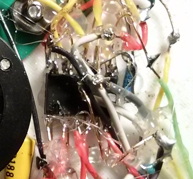
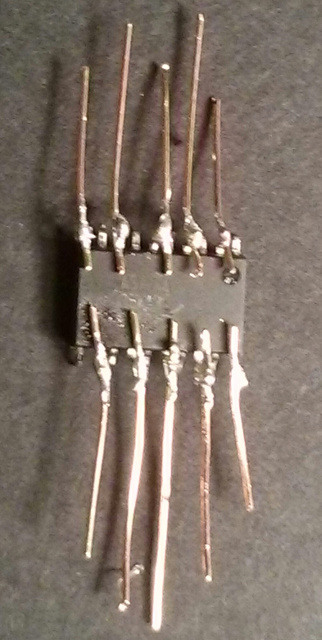
Huckleberry
Huckleberry's pins were also bent in an alternating fashion and was soldered to wires and jumper pins and encapsulated in hot glue, creating a pluggable module, like a cartridge, which is mounted in place.
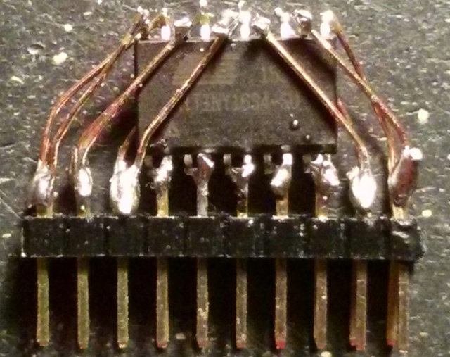
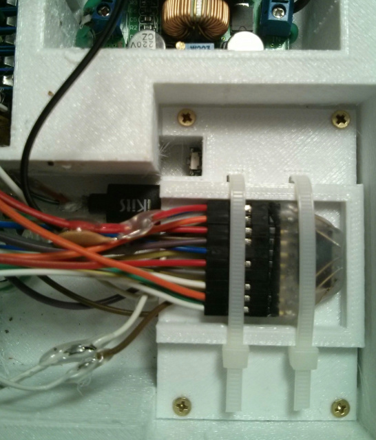
I didn't decide to add the ATtiny's at first. I had finally got Circuit Board B, the power regulation board, working and was basking in my success (as it took me two tries and two prototypes to solve all of the problems), and a few hours later, Huckleberry the hamster died and the excitement was gone. Later, I suddenly decided that the wiring was going to be too bulky to pass through the conduits I had designed, so I quickly added the two ATtiny 1634s to provide me with more I/O lines, as I had some of them on-hand already from my game.
I had always left myself the option of using the ATtinys but didn't make the decision until Huckleberry was gone (as if my subconscious was already mulling over the problem). And Sawyer the hamster died shortly after I completed the gondola Circuit Board C. In retrospect, if I didn't add the ATtinys at that point, I would have run into numerous problems down the line, so in some strange way they helped to make this project come to life.
I like to talk about interesting patterns and congruences that I see, and this is no exception. Huckleberry and Sawyer were two brothers, born and died close in time to each other, but they only lived together in the first year and remained separated in their own cages for the last 2 years. Male hamsters are solitary creatures and need their separate spaces (and it reduces the chances that a disease could spread between them) so they lived out their lives in large containers. They never saw each other after that but could probably hear, or at least smell, each other. Sawyer was the runner, Huckleberry was the digger. Sawyer went blind in his old age, Huckleberry went deaf.
So in the craft, Sawyer controls the gyro wheel, the main drive motor, and reads the CdS photocells, and Huckleberry controls the switching circuitry for the solar charging, batteries, and voltage boosters. Sawyer harvests the power, Huckleberry regulates it.
Both are I2C slave devices (limited by hardware) so they can't usually talk to each other directly (just like the hamsters) but they have independent lives. The Pi and ESP (I2C master devices) can initiate the conversations and relay the messages between them, if needed, but there is a special communication channel that I'll describe below.
There are three other intriguing relationships between the CPUs:
- Sawyer ran out of I/O lines mainly due to the high number of lines consumed by two motors (H-Bridge Brushed DC and 3-phase BLDC) along with their Hall-effect sensors, so I had to share one of the lines with one of the Hall-effect sensors, in addition to in-circuit programming. The MISO line (which is shared by both Huckleberry and Sawyer for SPI in-circuit programming) isn't used during normal operation and serves this purpose. It also controls an LED light when the Hall-effect sensor isn't activated (sinking) if the Pi and ESP have either relinquished control or have lost power. Huckleberry can also control this light.
- Sawyer, by default is configured to watch to this line for Hall-effect sensor detection when it drives the motor. But when it doesn't drive the motor, it is configured to interpret any line sinking as a signal from Huckleberry, as if Huckleberry is sending him a secret message.
- Huckleberry can also control the LDO (Low-Dropout Regulator) of the Huzzah ESP8266 board, allowing it to turn off all power to the ESP and anything powered by its 3.3 volt output. And the Pi cannot be turned on without the ESP. So Huckleberry determines the fate of all higher functions of the craft.
Just like the hamsters, the ATtinys are tiny creatures awake at night when the other chips are sleeping (they use such little power that there is no need for them to go to sleep). Late at night, near sunrise is the most precarious state for the craft, as it has been out of sunlight/solar power for the longest span, so in some cases the Pi has already shut off the Radio, the ESP has already shut off the Pi, and Huckleberry has already shut off the ESP.
But his brother Sawyer is still awake in the module next to him, keeping watch on the dark sky waiting to tilt the craft to the Sun, all on its own.
Huckleberry can detect Sawyer's work when it notices that electrical solar energy begins flooding in, and then it turns on power to the larger CPUs (the Pi and ESP). But the tiny chips can still go to sleep if they want: if the battery voltage drops too low and risks damage to the Lithium-ion cells, Huckleberry can make the decision to cut ALL battery power to itself and Sawyer, turning them off until the morning sun arrives, at which time they will come back online on pure solar power alone. They could be configured to save any important information to the internal EEPROM beforehand. (Hamsters, by the way, have the ability to hibernate, placing themselves in a state of torpor if conditions become unfavorable, which should hopefully never happen, a trait humans may have once had in our ancient past.)
But during those darkest of nights, when the Pi and ESP are offline, the blind Sawyer can still see (light intensity) and the deaf Huckleberry can still feel (vibrations). Sawyer, could, for instance receive Morse code messages via flashlight pulses on the CdS photocell and respond back by flashing the LED spotlight.
But Huckberry can feel those same Morse Code pulses through the tether, via the LIS3DH accelerometer interrupt. I call this my experimental Tethered Haptics Using Morse Pulses system and inverted my SIMTHEO Morse Code decoding algorithm and added it to both Sawyer and Huckleberry to allow a haptic channel to be created. Both CPUs receive the Morse pulses essentially simultaneously through an asynchronous, daisy chain serial bus through Huckleberry, and Sawyer responds by sending a vibrating pulse to the drive motor, to send a haptic message down the tether to be felt by a person near the ground. This forms a haptic communication channel that doesn't require any radio communication or smartphone, allowing a human operator to control the craft with only the two ATtinys in charge.
If, for some reason Sawyer failed completely, Huckleberry could still maintain power at a low level when the sun hit the panel at the correct angles, but it would have to sleep frequently, and the craft would be stranded high on the tether exposed to windy storms. If Huckleberry failed, Sawyer could still maximize solar power, but there would be no way to store it. The ESP should come up on its own if Huckleberry fails, but there would only be enough power for it and the Pi during sunny days, and it would have to carefully manage the motor power and radio, providing barely enough power during the brightest of days.
This seemingly orchestrated operation is profound, and it reminds me of all of the life forms in the world and how we live out our lives, being quite isolated and separated, yet we are interdependent on one another, all in cycle around our Sun, not realizing the high-level beauty of what we are creating.
Full In-Circuit Programming
I designed the circuitry so that all 4 CPUs and the radio can be re-programmed in-circuit while being outside, high up in the air.
- The Pi Zero W WiFi-link can be enabled to allow SSH console access to the open-source programming tools. This allows me to stop/start and reprogram all of the Pi code (the bot, the PBBS, the alias commands and packet config files). And, if temporarily connected to an Internet-enabled router, I can perform software and OS updates.
- Sawyer and Huckleberry share the same SPI lines but have unique reset lines to the Pi. I created scripting on the Pi that parses a single C source file, separates out the relevant parts that correspond to each chip, toggles the reset line for just that particular chip and then compiles and burns the new code to flash. This allows me to work with just once C source file while ensuring that I don't accidentally write the ATtiny code to the wrong chip, with potentially catastrophic results, since they are connected to different circuits.
- The ESP8266 can also be programmed via the Pi console and open-source tools. And, because the Pi can control critical GPIO lines on the ESP, it can also update its firmware.
- The flash code on the UV-5RA radio can be re-programmed on-the-fly which I've used extensively (and mention below in more detail), but its firmware is not modifiable.
The Reset Network
Since there are 4 interconnected CPUs that can be enabled/disabled for power management and/or programmed in-circuit, this created a lot of combinations that had to be mapped out and carefully wired, which I call the Reset Network. I had to be careful to make sure that competing devices that controlled the same logic didn't short out or lock out each other. In two cases, I created "bootstrap" arrangements to allow the circuit to keep itself powered while on, but I had to have some way of overriding this arrangement if needed.
Ten Temperature Sensors
Four DS18B20+ Sensors
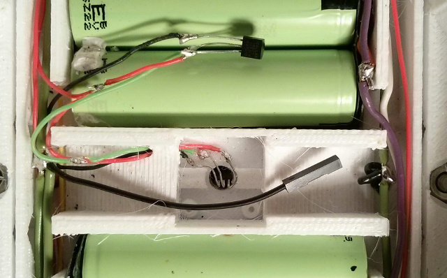
The Maxim DS18B20+ 1-wire digital thermometer is an amazing device for the price, like a little digital computer that can sense temperature. It requires only around 1 mA or less but uses only one resistor and one data line which can be used to read multiple additional DS18B20+ devices, and each one can be read independently of the others. It is fairly accurate (.5 C) and can measure temperatures from -67 to 257 F (-55 to 125 C).
Luckily, NodeMCU also contains 1-wire support for the ESP8266 and even specific DS18B20 support. I had trouble getting Python on the Pi Zero to reliably read the sensors by accessing the Linux file system. For some reason, the readings were often corrupted and only the first reading worked. Even BASH shell programs failed if launched by the Python script, and this occurred even if nohup was used. It was a strange issue that seems to be related to high CPU activity and/or Pigpiod, but when I run it from the shell directly, it works. So I created a cron script which saves the temp values to ramdisk every minute and then the Python program reads the values. This creates a lag in temperature readings, but I can always use the other sensors to look for fast swings. The DS18B20+ sensors are absolute sensors that can be used to calibrate the other relative sensors at boot, using offset values.
I incorporated 4 sensors (solar panel, main housing, battery box, and shaded outdoor). This allowed the Packet BBS and APRS to report outdoor temperature, allowed monitoring of the panel and main housing, and allowed active temperature control of the batteries.
LIS3DH Temp
The LIS3DH accelerometer, mentioned in more detail later, provides a temp sensor (which I used) and extra ADC ports (which I didn't use yet). Temperature calibration is important to get accurate readings from the accelerometer and is accurate to about 1 degree C, but this is not guaranteed.
Two ATtiny Temp Sensors
Like the LIS3DH, the two ATtiny 1634 microcontrollers have relative sensors that can be read but need to be calibrated against the DS18B20+. They are even less reliable than the LIS3DH, accurate only to about +- 10 degrees C. They have a gain coefficient and offset which is set at the factory that can be read via the boot.h library (after accounting for an undefine error on compile), but I decided not to use them as they are of little use and my calibration is good enough. The coefficient won't work well if the error is non-linear, anyway. The CPUs stay relatively cool in use, but it's possible that under heavy use they may raise their own temperature.
Pi CPU Temp
The Raspberry Pi Zero W CPU temp can be read, but it is higher than ambient temperature since the chip produces significant heat. The ESP8266 has similar internal temp monitoring, but this function has not been exposed to the API at the time of this writing.
Two Switched Thermistors
The two Lithium-ion battery banks have their own internal thermistors for monitoring temperature, so I kept them against the batteries, but since I only share one charging board, I switch them in and out to ensure each of the two battery packs is accurately monitored. I use a relay in this case, instead of transistors, which should prevent the thermistor voltages from being significantly distorted, skewing the charger.
Solar Power Subsystem
On August 21st, 2017, a total solar eclipse passed through my city of St. Louis. The last time such a thing happened was in 1442, before the European discovery of America 50 years later, only around a century after the Mississippian civilization, the mysterious builders of our immense mounds, like those ghostly Martians in Bradbury's chronicles, had disappeared. And just a few weeks later, on September 6th, 2017, while I was building most of the solar charging circuitry, region AR 2673 unleashed a massive X9.3-class solar flare and an associated Coronal Mass Ejection, near its solar minimum, the biggest in at least a decade.
The Sun is fascinating to me, an entity of near endless radiant energy, and the ultimate source of most of earth's energy reserves, locked away in the arrangements of matter. I first experimented with solar power around 1980 with a Radio Shack 150-in-one kit which included a single, tiny solar cell, but it wasn't until 2015 that I built my first real solar device, but it was very small and only needed about 5 mA. But TrillSat needs about 150 times more power... and bigger panels.
Based on the specs and current measurements using a multimeter, I got the standby current draw of the two master CPUs under 300 mA. I also created an arrangement whereby the Pi could power down both the ESP8266 and UV-5RA independently, or the ESP8266 could power down the Pi (and the Radio too, as it has no function without the Pi). And the power regulation microcontroller, Huckleberry, can power down the ESP. The Huzzah board luckily has a EN (enable) pin on its Low Dropout Regulator (LDO), which is pulled high by a 10k resistor to the highest input voltage. All Huckleberry, the ATtiny 1634, has to do is ground it to shut down the ESP8266 board completely.
The peak current during full-power transmit or driving the motors is much higher, so I made some assumptions about a typical daily duty cycle and then began selecting the smallest, most cost-effective solar panels that I could find (for both low weight and a small aerodynamic profile) along with battery storage to allow nighttime and temporary high-current operation.
In 2016, before our solar panel import tariffs were imposed, the most inexpensive solar panels that I could find retail in small quantities in the US were those incorporated into Solar USB chargers from Chinese manufacturers (the kind that fold up in a PVC fabric case and do not contain a battery). Not only do these contain solar cells, they also regulate the voltage to 5v USB levels, and many of them also contain circuit boards that optimize power transfer. This eliminates the need (and extra cost) to purchase a solar charge converter. At first I looked at rechargeable Lithium-ion USB powerbanks with integrated solar panels in a weatherproof case, which were very inexpensive and are great for emergency use, but most of them were not designed for a full a day/night charge cycle. They had very small solar panels in relation to the battery capacity, so a 10,000 mAh powerbank might take over a week to charge under a full sun. So I needed a larger solar panel power-to-battery capacity ratio, minimizing the weight and cost at the same time.
The efficiency of the solar panel is a function of its current draw, and this can be altered by the circuit in some cases to increase efficiency. I've seen 2 types out there, thin film and monocrystalline, with the former being less durable and less efficient, but better in the shade, and monocrystalline lasting longer but requiring direct sunlight in most cases. Because I needed both durability and efficiency (it will be outside and the panel size must be as small as possible), I went with monocrystalline. I was lucky to find a 14w version for $32 that was advertised to contain SunPower solar cells.
The SunPower cells were invented at Stanford University and made by a US company, and have broken the world record on efficiency, at somewhere around 21.5% or higher. As I was writing part of this article, the Swiss Solar Impulse 2 solar-powered airplane was in-flight in its world-record journey to circumnavigate the world using only solar power captured by SunPower solar cells. However, the ones that I have don't look like their famous copper-backed Maxeon cells and are probably a low-cost version, perhaps the P-series with less efficiency.

The solar charger I purchased was made by X-Dragon, and it specifies >23% +-2 solar energy conversion rate in its manual. Using a hobby knife and aviator snips, I disassembled it to remove 4 solar cells that were sealed, covered in transparent PET protective plastic, and sewed in place.
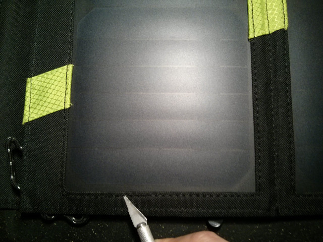
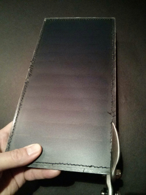
There were very few recognizable IC's on the tiny circuit board (probably of Chinese origin with little English documentation). The unit consists of 2 rectangular panels containing 2 large square cells each, sealed inside. I assume they are internally connected in series, producing around 7 watts per panel. On the backside, these two panels are connected in parallel to produce around 14 watts.
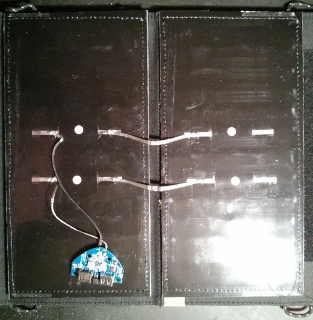
Each square cell appears to contain 5 busbars, which seem to create a series arrangement of 6 smaller cells. Since silicon monocrystalline solar cells usually output about .7v, then 12 in series per panel = 8.4v. This concurs with what I read on my multimeter (over 7 volts) and there might be some additional internal diode losses. I assume therefore that the internal 5v voltage regulator is probably some type of buck converter and doesn't activate when the panel voltage is less than 5v. This was corroborated by the fact that the regulator would not turn on when I covered up the ends of the rectangular panels even under bright light (as it would have reduced voltage).
I then arranged them lengthwise and reconnected them using two layers of flat copper foil tape covered by Kapton tape for insulation. They meet in the center wires so they can be fed into the battery box at only two points to minimize moisture. The copper tape has a large surface area which aids cooling.
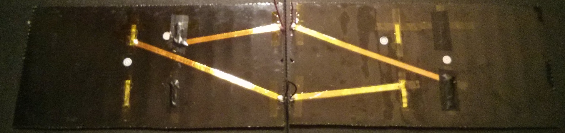
It had to be flat to fit flush with the battery box and the copper tape, and so the screw heads had to be inset into the battery box frame, forcing the aluminum to bend into the screw holes. The hole in the very center is for a temp sensor.
And here is the assembled panel (minus the temperature sensor which was installed later) mounted in the trim, sealed with acetic-acid free silicone caulk and covered with clear acrylic.

Floating Solar Panels
One of the reasons solar-powered satellites and spacecraft look like they do is because of the lack of gravity. Solar panels need to expand to cover a large amount of area, and they can easily do this in space, but if they were on Earth, those panels would act as long levers and gravity would tear them down, breaking their supports and/or hinges. On Earth, you rarely see long arrays of solar panels controlled by a solar tracker. The mechanisms would get too impractical, and so they are usually split up into multiple units. But in space, they can be enormous.
NASA's Juno spacecraft has 3 long panels that are 9×29 feet in size↗, extending its span to more than 66 feet.
In my design, I decided to hang the solar panel along the rope to spread out the weight, separating the panels and orienting them into a single line of 4 panels instead of the original 2×2 design. The motor drive simply nudges the panel up a ramp or lets it slide freely downward, and the panel pivots on its midpoint. However, due to the catenary curve the rope assumes under the weight of the craft, the forces and friction were unexpectedly strong at the ends of the panels, and the center support had to be rigid enough to prevent them from flexing, while maintaining a fixed solar angle. Luckily, under actual motor drive, the friction isn't an issue because the capstan suddenly tightens the rope on the side it is moving towards, relieving much of the guide friction on that side. The taut nylon paracord was able to slide along the PETG guides fairly well. It is also interesting that the higher the rope tension, the lower the guide friction and the higher the capstan friction (which is good), but the friction increases where the rope changes direction and routes around the drive motor. Because I used ball bearings at these points, the friction doesn't increase at the same rate, so the system works fairly well.
Orienting the panels longitudinally along the rope also spreads the area exposed to aerodynamic drag (wind) and aids cooling.
Spiral-Axis Solar Tracker
Vertical single-axis trackers employ a vertical pole, changing the azimuth. But my panels are rotating around the angle of elevation, changing the characteristics, called a Tilted Single-Axis Tracker, or TSAT↗, allowing me to capture more sunlight on winter mornings and evenings (tilting closer to the horizon).
There is a 2012 research paper published in the International Journal of Modern Engineering, entitled Analysis of Solar Panel Efficiency Through Computation and Simulation, written by Hongyu Go and Mehrube Mehrubeoglu, where they created a computational model/simulation of the sun and then analyzed the results. They concluded that the TSAT has the highest efficiency at 97.2 very close to the 100 efficiency of dual-axis trackers and well above the efficiencies for seasonally-adjustable fixed panels (SAF) and Horizontal and Vertical Single-Axis Trackers (HSAT and VSATS). Incredibly, their measured 97.2 % efficiency was independent of latitude, unlike the others they analyzed.
The angle of the rope should be tilted so that the panel is facing the intersection of the celestial equator on the local meridian at noon. The local meridian is the north/south alignment, and the altitude of the celestial equator (its angle from the horizon) is 90 - the latitude. So by simply using my latitude of 38.6 degrees as the angle in a right triangle, the hypotenuse faces this intersection in the sky. This can be fixed and does not need to be changed throughout the year and is, rather conveniently, very close to a 4:5 ratio right triangle.
However, due to the weight of the craft, a surprising thing happens: even under high tension, the rope takes on a catenary curve and the Y-axis tilt changes as the craft climbs, and decreases as it lowers. When the craft tilts, it must also move forward or backward, due to the linking of the two functions, similar to turning a nut around a threaded rod. You could think of the rope being the dimension of Time, the rod, and the rotational movement rocking around it, like the nut. But in this case, Time is not a straight line, but more like a rod bent upward due to the catenary. Certain angles are only possible at certain positions on the axis.
This is why I call it a "Spiral" Axis Tracker and not a Single Axis Tracker, and you could think of it as a traditional axis being curvilinearly bent into a new coordinate system.
In one of my past essays, I wrote about how all of our actions take us that much farther into entropy, the arrow of time, and that I once programmed a videogame on the TI-99/4A where my spaceship could go up and down to avoid asteroids, but each steer also took it forward into the asteroids path. I had made a error in my programming, yet I decided to keep the error intact, as it made for a more interesting game. To keep costs low but also provide functionality, early single-channel RC cars were the same way--you could steer the car, but only by going into reverse, and they were always moving and never stopped...
This spiral overlaps some of the functions of a true dual-axis tracker, allowing it to theoretically achieve close to 100% efficiency if the craft is "parked" at various points on this curve at different times of the year. Erecting the rope at a precise angle is not critical since the accelerometer can detect its angle allowing the craft to park itself as needed. One of the interesting things about spirals is that they can be thought of as 1-dimensional lines bent through multiple dimensions.
Because the system is hanging on a tether, as I mentioned earlier, wind and motor operation can cause pendular motion that can temporarily change the orientation of the panels using the tether as the roll axis, cutting efficiency. The use of slow startup PWM motor control routines reduces the motor-induced motion and the gyro can also be pulsed in the opposite direction to counter the drive motor, being on the same axis. The motor can be stepped at various time intervals (and not continuous) only when the time is appropriate or sensors detect a major difference. This reduces motion and conserves battery.
However, TRILLSAT-1 ended up weighing 3.76 kilograms (around 8.28 lbs), a weight greater than I expected and so the panel doesn't tilt a full 180 degrees to each side, as I don't want to increase the weight further or extend the length of the planetary rod. Thankfully, the efficiency equation is not linear, due to trigonometry, and so I don't need to. Lambert's cosine law tells me that the energy of direct sunlight is related to the cosine of the angle. So if I can just get it to tilt significantly, the gains will be much greater than barely tilting it, and I don't lose as much over a full tilt. And there is, of course, indirect energy hitting the panel, which also contributes. In other words, it's not just the angle of the light affecting reflection/refraction, its the surface area that photons can reach, which changes when tilted. For example, when you look at a flat television display at an angle, that thin screen is dimmer overall than the same, much larger screen observed from the front, because you're only looking at a sliver. MotionPicture cinematographers have known about this for some time, and some light meters even have "cosine correction" filters.
It has always fascinated me that triangles (although made from 3 lines) actually have very non-linear characteristics due to their enclosure, the ratios between their lengths and their angles, which are related to Pi, and circles.
Two LDR Sensors
The ideal position for the solar panels can be calculated by the time of day, time of year, and latitude, and if the clock was set correctly by the operator, the craft can rotate to the correct angle via the Hall-effect sensors/accelerometer.
However, I also added two CdS photoresistors (LDRs) offset 45 degrees to the plane of the solar panel which can observe the sun directly and compute the angle of the sun via the same Lambert's cosine law (with some minor adjustment for the offset angles). This allows me to estimate solar intensity (and current for the charging algorithms), estimate cloudy weather conditions, and could even be used for signaling (initiate Demo Mode, perform emergency stop if the user covers it with thumb, receive Morse Code, etc).
Due to the translucency of the white PETG plastic, I have to line the interior of the LDR Tubes with an opaque material to prevent reflected light from entering the CdS sensors sideways, skewing their readings.
Optional Solar Reflector
I don't plan to add this, but this is a trivial efficiency boost if sunlight is a problem: A small aluminum reflector can be mounted below the panel (perhaps secured to the Qi Dock) tilted at a wide angle to allow morning and evening sun to reflect onto the panel, but not noon sun. Because the panel is long, as the sun rises, the light moves along the length of the panel until it is past the angle of reflection. This directs more sunlight to the panel in the morning when electricity and heat are most needed, since battery power has been depleted and the battery box is cold. It prevents overheating the panel at noon, and then also provides an extra boost with the evening sun. The tilt of the panels automatically keeps the mirror at the correct angles, but it would expose the unit to more wind.
Hanging Zepp Antenna
Antenna theory is extremely complicated and I do not claim to be an expert. The concept of antenna "gain" in an interesting one, and is not related to the concept of transistor gain, for example. It has to do with how much the antenna is focused and how the RF is "squished". Emitted power is the same for antennas of different gains, but increasing the gain in a certain direction can help you use the power more efficiently.
What I need is an antenna that can reach the people around me. Since I am already at a fairly high HAAT, and the tree takes it up higher, I have good line of sight to antennas and people around me. But the "take off angle" is not as low as it could be, and there are people far away that I might not be able to reach if some of the energy is wasted by being directed upward. The radiation pattern and even the impedance change as you move the antenna up into the sky away from the ground. Sometimes a high antenna is not what you need, but in my case, with low-power VHF, line-of-sight is more important than radiation pattern.
On Christmas 2016, I received the 23rd edition of The ARRL Antenna Book from my ham "Elmer", a thoughtful gift and a wonderful book, and have been studying antenna theory. I knew many of the concepts after studying for my General class license, but I needed more detail for this project. Antenna theory is perhaps more complicated than all of the elements of this project combined, in the oscillating domain of analog waves, outside my discrete comfort zone, which is reflected in the girth of the tome.
One problem using a standard 1/4-wave ground plane antenna is that high-voltage/corona effects could come close to the Radio Box. One problem with using a 1/2-wave dipole is getting a low take-off angle and matching the impedance to 50-ohms. And the 5/8-wave antenna was even more complex and I don't have an antenna tuner.
I haven't yet built a 2-meter antenna for TRILLSAT-1 at the time of this writing, which is why it wasn't depicted on the initial diagrams and photographs, and I don't know which I will build yet, but the J-pole "Zepp" antenna design does have a lot of benefits in this case, as it can be hung, being end-fed. This is based on an old antenna design first patented by Hans Beggerow in Germany in September 1909 and hung from Zeppelins, keeping the RF energy away from the explosive hydrogen and directing it downward. Curiously, Albert Einstein was a German patent office clerk at that time (resigning from this job the following month to become a professor at Zurich University), and I wonder whether it came across his desk or even influenced his ideas on electromagnetism.
As mentioned earlier, in many ways, TrillSat behaves like a zeppelin or airship, floating on an axis. I like the light, inexpensive, and flexible twin-lead design by Edison Fong called DBJ-2, first published in March 2007 in QST magazine, mentioned on page 16-7. Such an antenna would allow me to coil it up and store it in the Ark with the rest of the craft for easy storage and transportation.
The aluminum panel would sit near the hanging antenna, however, which (if not grounded) could act like a parasitic element, a reflector, changing its characteristics when the craft is tilted, so I'm not sure how well it would work, as the J-pole is susceptible to near-field effects. It has a 50-ohm impedance at ground level, which matches the UV-5RA. But if you raise it up into the air, the impedance increases and it becomes less efficient. And the hanging antenna cannot hit the orbiting planetary mass, which would become an issue at high pitch angles unless some kind of offset or standoff was added. I've thought about mounting the J-Pole above the craft on a rod and letting it hang down, and this rod would also help to counterbalance the craft, increasing its tilt angle, but it would also add some instability.
There is also the factor of the tree itself. Trees in the spring/summer with lots of water-filled leaves will attenuate line-of-sight 2 meter signals. So, the antenna should be kept_away_ from tree or above it, if possible. In my case, I am using the tree for elevation and am trying to find a happy medium. This can be mitigated by moving the craft away from the tree and slightly lower than the bulk of the leaves. I would try to position the J in the J-Pole to face North as this provides a slight gain boost toward the tree where it is needed most to get through the leaves. This type of antenna, however, is about 4 1/2 feet (1.4 meters) long, negating some of the benefits of raising it, but the cost, weight, construction simplicity, and gain benefits are making me take a hard look at it. Because it is flexible, the craft can also "land" without damaging it, birds won't land on the radials, and it is dual-band.
I may build more than one antenna, a 1/4 wave ground plane, where I can adjust the radials to match the impedance at elevation and the flexible J-pole, but I don't know at this point as I have left the antenna to the very last phase of the project, since I can still test it over-the-air using simple 50-ohm dummy loads. I have done some rudimentary modeling using 4nec2 under WINE in Linux.
Six Radio Links
There are 6 different radio links in the craft, in descending order of bandwidth:
- 2.4 Ghz 802.11n (Raspberry Pi Zero W) - 72 Mbps max
- 2.4 Ghz Bluetooth 4.0 (Raspberry Pi Zero W) - 3 Mbps max, currently disabled, as it is not needed and allows me to use a better UART
- 2.4 Ghz 802.11n (ESP8266) with TCP bridging limited by UART and/or Lua interpreter speed - around 9600 baud max before corruption occurs
- 70 cm amateur radio - audio monitoring only - 2400 baud packet possible, but not used since uncommon, 9600 baud not possible with radio audio circuit
- 2 meter amateur radio - audio monitoring and 1200 baud packet and APRS
- FM radio - audio monitoring only
A Smaller Radio Interface
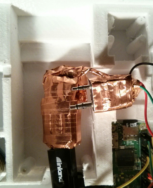
I redesigned and miniaturized the Baofeng UV-5RA radio interface (audio + data + PTT) that I designed for my earlier PacketRadio project. Combined with a different USB sound card, it is cheaper, lighter, and small enough to fit underneath the UV-5RA radio itself when the battery is removed. I can even 3D-print a hollow battery box and mount the interface inside that box, essentially incorporating it into the handheld radio itself. However, in this case there was no need to do that, as it would just increase weight, so I nestled the unit underneath the radio. Removing the black plastic case from the UV-5RA helped to make the interface thin enough to allow me to do this, while at the same time removing additional weight.
The interface is underneath the large metal ground plane of the radio, helping to isolate it from noise, and I wrapped the entire interface in copper foil tape, which is grounded, acting as an RF shield.
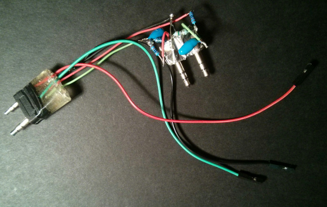

I also controlled power to the radio directly by interfacing to its tiny power socket on the PCB.
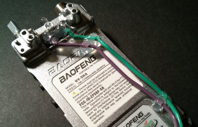
UV-5RA Voltage Conversion
The UV-5RA lists a nominal 7.4v supply, which closely matches the voltage of two NCR18650B cells in series (7.2v nominal). When fully charged, however, the Baofeng battery has a much higher voltage than reported on the label, over 8 volts, so it appears that these are just nominal values.
Why Not LoRa?
LoRa is an interesting long range, low power, spread-spectrum "chirping" wireless technology. At the time I started the project in early 2016, the less-expensive ESP32 LoRa boards didn't exist (in fact the ESP32 itself didn't exist). These LoRa boards are still fairly new and much more expensive than the ESP8266, and two of them are needed for communication, since smartphones currently lack LoRa radios themselves. In other words, to allow XMPP texting to a WiFi-enabled smartphone over LoRa, a LoRa to WiFi gateway would need to be constructed and somehow added to the smartphone.
This is not out of the question, and due to its range, low power, and light weight, LoRa also has the potential for replacing the VHF packet radio completely, and a PBBS could be run over LoRa, but there are some drawbacks. From what I've read, although LoRa uses higher frequencies than packet, for a single device it has a very low bandwidth, just a few bps, much lower than the already-low 1200-baud packet that I am using, as it was designed to communicate with huge numbers of LoRa devices using very little power, not allow one device to hog the spectrum. And the higher the bandwidth that can be achieved, the range must be further decreased, negating one of its primary benefits (range at low power levels).
So, for human use, not just IoT devices/sensors, packet is still very usable for a small PBBS and text messages, and there are many hams that still have the necessary equipment to make the connections. There are still packet digipeater networks in place.
So I decided to leave LoRa as a future experiment in the form of the Planetary Space Pod instead, a sub-project of this craft that I made adjustments and allowances for in the design, including the Qi Dock and the design of the Planetary Assembly.
Battery Redundancy, Capacity, Charging, and Monitoring
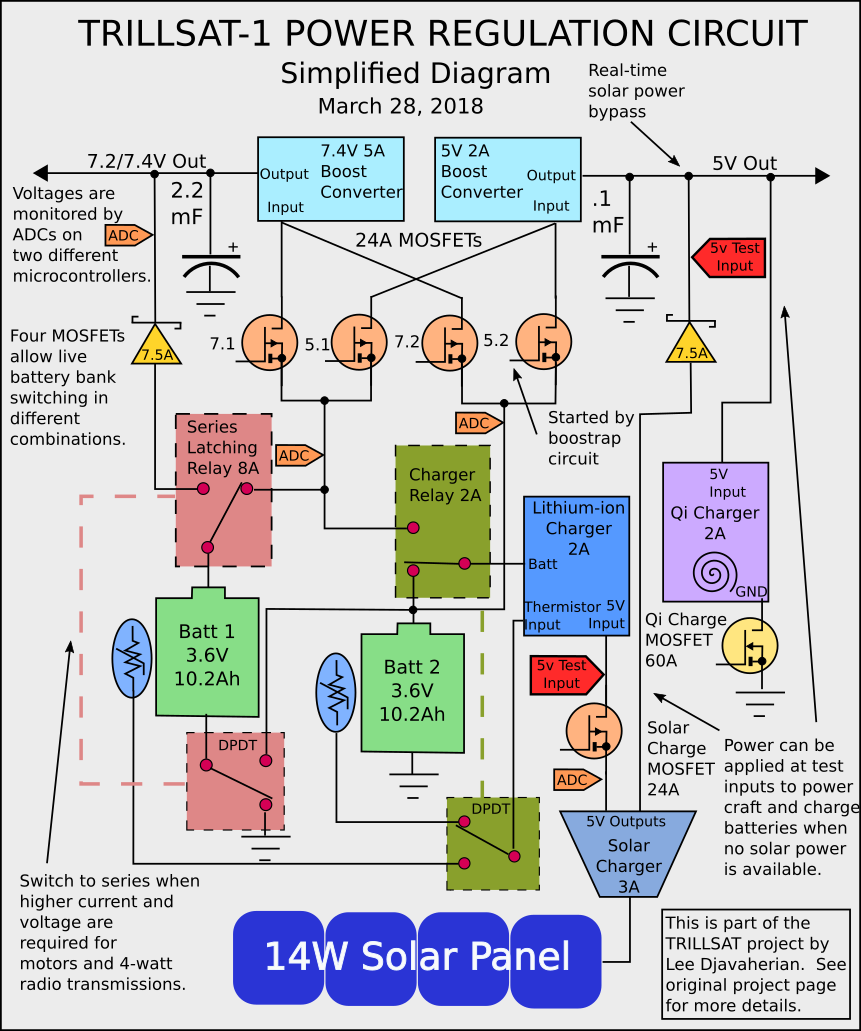
(Click diagram to enlarge)

Similar to the solar panels, I also needed cost-effective and lightweight batteries and Lithium-ion was my technology of choice, having extremely high energy densities. The cylindrical 18650 cell is especially cheap, but there are a variety of different manufacturers (of unknown quality) and the both the advertised and actual capacity varies from manufacturer to manufacturer. However, Panasonic NCR18650B cell, made in Japan, has an enormous 3400 mAh capacity per cell (3350 mAh typical, according the the datasheet, and its actual capacity has proven to be very close). I have read that the Tesla model S automobiles were powered by 7,104 cells very similar to this cell.
Well these cells are more expensive than Chinese-made 18650 cells, and then there is the extra cost needed for the charge controller. Charging Lithium-ion cells isn't a trivial matter, as their high power density and flammable electrolyte make them a potential hazard. Unfortunately, this is the eternal quandary of using any stored fuel or energy source whether or not it is chemical (petroleum, batteries), electrical (transformers, capacitors), or mechanical (flywheels, gravity)--there are more forms, this is not exhaustive. Whenever humans concentrate or contain energy, creating a highly-ordered state, it must be carefully regulated and monitored. In effect, we are fighting against the natural tendency of the universe to move to a state of entropy/disorder. Even information (another highly ordered state) follows this pattern. But, by being creatures of both energy and information, we humans have immense power to impart order into the universe. In fact, our sole existence is defined by the order in which we are arranged and that which we continue to arrange.
Luckily the Lithium-ion voltage under charge has consistent characteristics. But they require a fairly smart controller to monitor this voltage as it charges and then cut off the charge when it reaches a certain voltage. It also needs to monitor the temperature of the cells. And there also needs to be some type of discharge controller, as the cells need to be disconnected before they discharge completely, or they can become damaged. And the rate of discharge has to be monitored to avoid over-current. The solar USB charger puts out 5v, but Lithium-ion cells cannot be charged at this voltage. Also, much of the craft's circuitry (the radio, the L6234 motor controller, the H-Bridge) requires a voltage higher than the 5v solar charger can directly provide.
In a conventional battery, the cells can be placed in series to double the voltage, but charging in series is difficult, since Lithium-ion cells have to be treated with individual care which requires additional charge controllers for each cell (and them some way of taking each cell out of series to charge). Parallel arrangements aren't as critical, and the cells will reach an equilibrium by discharging into one another, but this doesn't help with voltage-matching. So a voltage boost-converter circuit or IC is usually required.
I came up with a few earlier designs to arrange 4 18650B cells in parallel, producing 13,600 mAh and then using a boost (or step-up) converter board (with a custom IC) to reach the desired voltage. But a charge controller is also required, so this creates additional cost, especially if thermal monitoring is needed.
However, to add to the complexity, it is difficult to charge a Lithium-ion cell while using it, which is what I would need to do if it were to operate in the daytime, or else all of that solar energy would be lost (and the batteries would soon deplete). A battery under load does not produce the voltages that the controller expects to see when fully charged, and it can overcharge. Some ICs are said to be able to handle this (called pass-through), but these ICs are generally more expensive, and for longevity, the rule of thumb is to refrain from using Lithium-ion while charging it, if at all possible.
The Perils of Dismantling a Power Bank
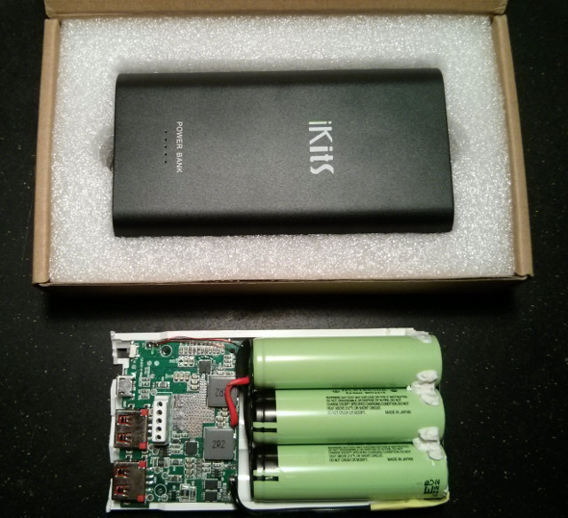
So I decided to drastically reduce the cost by purchasing a USB power bank, which is essentially a self-contained set of batteries (usually in parallel) with a built-in charge-controller, protection circuitry, and a 5v boost converter. I found one made by iKits which contained 3 Panasonic 18650B cells capable of 10,200 mAh, less capacity than I would like, but it had to be as light as possible. It could also handle the current levels needed by the system at full-power and could accept the charge rates provided by the solar cells.
The iKits bank contains thermal monitoring and a power switch. The switch can be controlled using 3.3 volt logic (by simply setting the switch to a logic low, or ground) but it was too small for me to solder and wasn't necessary since the powerbank performed most of its functions automatically, and for this reason, many powerbanks available today don't even have a power switch at all. When the iKits unit detects current on its 5v lines, it powers on, but if the current levels get too low, it will power off again. And if it detects current on its charge port, this takes priority and it disconnects all power output (probably to protect the batteries, as I mentioned earlier).
Well this presents a problem, since I need to power the craft at ALL times (it cannot go down during charge), so I used 2 powerbanks and switched between them; while one is charging, the other powers the craft.
At first, I tried to control the solar power coming in using MOSFETs to ensure that the the powerbank in use didn't auto-shutoff its 5v USB output under sunlight. But I ran into some fairly significant problems. Without using the power switch, the powerbanks will only turn on when they detect significant current. So in a full-off situation, where the batteries died at night, and in the morning the ATtiny 1634 (running on pure solar power) tries to reactivate the battery banks, it has to pulse the powerbanks with enough current to keep them on, and keep pulsing them so they stay on. Other people have built such circuits and it is not very difficult to do with a 2N2222 and a small resistor (keeping the duty cycle low), but the problem is that the current detection appears to use a low-side current sense resistor.
What this means is that the ground line coming out of the USB 5v ports is not the same as the battery ground but isolated at a higher level. When I connected these two grounds, the current sense ability stopped and the unit started to buzz (as I was essentially creating a short across the current sense resistor) and the unit thought zero current was passing through even if I tried to draw max current. You can't just replace the current sense resistor either (one of larger parts on the board) but would need to intercept the circuit that reads the resistor and then fool it with a different voltage. The circuit was far to small for me to attempt this.
The other option is to completely separate my 5 volt ground plane from the battery ground plane, but this is impossible if I use BJT and MOSFET transistors to control motor power since they require common grounds at various points. So I would have had to insert galvanic separation (such as an optoisolator) at each MOSFET junction and then run a separate 5v ground line everywhere, increasing the number of wires in the craft. I've used optoisolators before, first using the quad ILQ-74 on my Commodore 64 PBX project back in 1991 when they were fairly exotic, so I am familiar with them. But switching them directly from Raspberry Pi or ESP 3.3v GPIO lines to control PWM motors requires logic-level optoisolators with fairly high CTR (current transfer ratio) along with relatively high switching speed. I did some preliminary research and found the SFH618A series have a nice CTR for the price and might work at the low PWM speeds I needed but they were still over 5 times more expensive than the common 2n3904. But as I thought about it, I hated the idea of isolating my ground planes. Normally, if your design is good, common ground is desirable from a cost/simplicity standpoint. On the C64, I used galvanic isolation to interface into the public telephone system (something I could not control that could produce high voltages) but here, the circuit is under my control and voltages should stay fairly low.
In a way, galvanic isolation is like a Rube Goldberg machine, an out-of-band process that jumps from band to band, system to system. Instead of dealing with one system, you're now dealing with 2 separate systems that are still connected through information. This gets philosophical; when do you combine, or when do you separate? I had already chose to separate when I used the relay (another form of galvanic isolation), taking the pragmatic approach to solve the problem, but my subconscious nagged at me to draw the line on the optos. In the holistic design of the entire craft, they just didn't feel right.
I also ran into the problem of knowing how much charge was left. Each powerbank has a series of 5 blue LEDs which drain power when the unit is in use (charging or discharging). A phototransistor could have been added over the second-to-last LED to let me know when the powerbank was in the last 19% of charge, but this is a fairly crude test. (In the end, I decided to use the ADCs of the ATtiny 1634 to read the voltage.)
But then I couldn't tell if the powerbank was actually on, which was critical if I was switching the entire system over to the other bank. At first, I tried using a simple 10K/20K voltage divider to drop the USB 5v to 3.3v levels, but the powerbank never fully turned off (when the ground planes where connected) but it dropped somewhere under 3.7 volts (varying) as it remained active, perhaps sensing current for its auto-on feature. And I figured that I couldn't pull this phantom voltage down to zero without triggering it to auto power-on (if the ground planes were separated). So even with the voltage divider, it remained over 2.4 volts when off, still a logic high. I tried adding reverse-biased 4.7v 1N4732A zener diodes in series, hoping that they would act like a 4.7v high-pass filter, providing a crisp 5v logic high, but there was too much leakaqe at low current levels. Apparently the larger 1-watt zeners are not sensitive enough, but even so, a zener is a non-linear device that has some weird characteristics at varying current levels. Then I tried adding a LM393AP dual comparator IC, setting the reference voltage to 3.7 volts, where a 5 volt would show a logic high and the standby voltage would show a logic low, but it didn't work. The common-mode voltage (3.7 volts) has to be within 1.5 volts of the supply (5v) but it was only 1.3 volts away, even less when the batteries were at full charge. So in order to read the comparator, I would need to boost the supply voltage to 5.7 volts or higher. I almost did this, since I also put a 7.4v boost-converter in place for the radio/motor circuitry.
But then I decided that the whole ordeal of managing these finicky power bank regulators was getting out of hand.
Four DC-DC Boost Converters
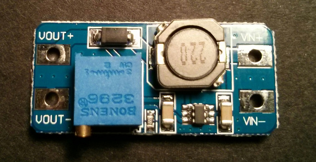
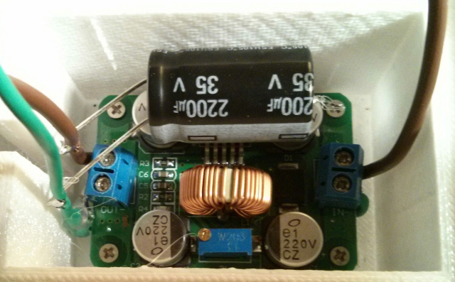
So I decided to completely bypass the built-in 5v boost circuits in the USB powerbank (which use an internal 3-amp MT5036 step-up converter chip) and only use it for charging the batteries. I then added a 2-amp MT3608 chip instead, very inexpensive, efficient (with pulse frequency modulation), and small, and the circuit board was also small. I had originally bought it to supply 7.4 volts to the Baofeng UV-5RA radio. Early on, I decided not to use the Lithium-ion battery that came with the UV-5RA (for weight and complexity reasons), but the MT3608 couldn't supply the current needed on transmit (and had to use a less-efficient 5-amp LM2587S-ADJ instead). The MT3608 has an enable pin 4, which I excitedly tried to desolder from the board (which was connect to V+ input) so that I could ground the pin to turn it off, but I ended up breaking off the tiny pin. It was so tiny that after I soldered on a tiny wire, the wire acted like a lever and broke the pin completely off, destroying the board. So I had to buy a second one, and this time I left the pin permanently connected to its on state and decided to use a MOSFET to control power to the board. Using this board had several benefits: it eliminated the cumbersome USB wiring and the extra ground plane wiring, eliminated the need for optoisolators, eliminated the need to create a pulsing circuit to keep the current high, eliminated the extra current draw from the LEDs during discharge, and eliminated the potential for any accidental auto-shutdown if the current sensor suddenly dipped to low. However, it also eliminated the check on the battery voltage to auto-shutoff if the batteries drained, so this required that I monitor the batteries myself, which I delegated to the ADC power regulation ATtiny 1634 microcontroller, Huckleberry. And Huckleberry was running at a higher Vcc voltage, so its ADC could read the battery voltages directly without using a leaky voltage divider.
So two boost converters were added, the MT3608 for 5v, and the LM2587S-ADJ for 7.4v.
Again, the iKits charging board contains its own 5v converter, which I left unused, and since the L6234 also has its own charge pump, this brings the total number of boost converters (that can actually be used to 4).
So the craft has several different voltage levels that it can utilize:
- 1.1 volt internal ADC reference
- 3.3 volt logic
- 3.6 nominal battery voltage
- 5 volt logic
- 7.2 volt series nominal battery voltage
- 7.4 volt boost converter
- 8.4 volt solar panel line
- 10+ volt charge pump for motor driver IC
Series Mode
The current draw of motor is so high, that it, in combination with the UV-5RA transmit current could exceed the 7.4 volt boost converter's 5 amp rating, so I decided that for high-amperage operations, I would temporarily switch the 2 Lithium-ion battery packs in series and then switch out the 7.4v DC boost converter. Normally, during the day, the radio circuit will operate on the 7.4 volt boost converter from one battery bank while the other one charges. But when it is time to drive the high-current motor, bank 1 can be placed atop bank 2, raising it to 7.2 volts (nominal) and the boost converter can be disconnected.
I realized quickly that a DPDT 8-amp electromechanical relay was more appropriate than the MOSFETs in this case, since I needed it to switch at "zero" resistance (or as close as possible) so that it would not skew the precise voltage measurements of the charging circuitry or skew the ground plane, and I also needed to disconnect the charge circuitry from the top battery to prevent possible damage from the higher 7.2 volts that it was never designed to see. Most of the USB charge circuitry is not isolated, so in order to prevent short circuits I had to fully disconnect the top charge circuit. It is a latching "bistable" relay, which means that it only needs a short current pulse to switch states and then requires zero power to maintain that state. It is polarized, but the common terminal is positive, allowing low-side NPN transistors to easily activate the individual coils. Low resistance, high-current, zero power--bistable relays are neat things.
This has an interesting benefit: at night, of course, there is no solar charging at all, so both battery packs can be used simultaneously and kept in a series orientation. The 7.4 volt boost converter can be turned off completely, saving power and decreasing noise/ripple, with only the 5v boost converter on the bottom 3.6 volt bank. The ESP8266 can shut down (or be put into sleep mode) and be restarted by the ATtiny if needed. Huckleberry's ADCs can read the voltages when in parallel, but when switched out into series mode, only the ADC on the ESP can read the higher voltage with its separate voltage divider. The system shouldn't be left in series mode when shutdown, as the voltage divider will leak a tiny current, so I've added precautions to switch to parallel mode during shutdowns whenever possible.
If the 7.4 volt boost converter isn't switched off for some reason, it has diodes and a feedback sense on its output and will auto-regulate to the battery series voltage.
The high-current series mode also means that the bottom bank will drain faster than the top bank, making the bottom bank the limiting factor. When the bottom bank, bank 2, is drained, the circuit is switched to parallel mode and run on bank 1 in a low-power mode until morning. If the power levels drop too low, Huckleberry will cut off all power and await direct solar power. This also means that the top bank will run at a slightly higher voltage than the bottom bank--not a great idea but okay if used sparingly and the batteries are charged separately during the next daylight cycle.
This gives me interesting options to switch power around, a fun exercise that reminds me of how NASA had to manage power on the Spirit Mars rover. The total battery capacity is 20.4 amp-hours at 3.6 volts.
The USB Data Lines
USB power standards are constantly changing, and at the time of this writing, there is a new 2.4 amp mode (which the iKits powerbank supposedly supports), but it is difficult to find information on this. The USB D+ and D- data lines are re-purposed in this case to tell the connected device the max current it can support and the device itself manages its current draw. The iKits powerbank puts out around 2.7-2.8 volts on its D+ and D- lines, but these are not needed for the Pi Zero W, as they are left unconnected. However, I did connect the D+ and D- lines on the iKits input to the solar panel regulator to ensure that the powerbank itself charged at max current from the solar panel.
Controlling the Charge
I put an NDP6020P logic-level MOSFET between one of the solar panel's USB outputs and the powerbank's input so that I could shut off the charging, as the board will automatically begin charging (and will disable its own internal 5v boost converter, which I may some day use) if it detects input power. I had to make sure the MOSFET was on the 5v line and not the 3.6v battery line as to not interfere with the charging voltage.
If SOLAR_CHARGE_MODE is active, Huckleberry will perform the periodic routine:
- If bank 1 is greater than bank 2 by more than 200 millivolts (.2 volts):
- Move the system's boost converters over to bank 1
- Charge bank 2
- If bank 2 is greater than bank 1 by more than 200 millivolts (.2 volts):
- Move the system's boost converters over to bank 2
- Charge bank 1
Ideally, Lithium-ion batteries should not reach full-charge, and so picking a lower voltage and keeping each battery around that voltage also helps to increase longevity, vastly increasing the number of charge/discharge cycles. The brief time that the two power banks are in parallel should be acceptable as long as the batteries are close in voltage, since they just double the current (voltage remains the same). However, they shouldn't be run in parallel for very long to avoid any mismatch differences in battery voltage.
I made some logical assumptions which I will apply in future algorithms:
- The sun only shines during the daylight hours (which can be determined by the clock, if accurate).
- The photoresistors that I added to the solar panels (more about this below) give an indication of the intensity of the light reaching the panels (since I didn't add any current sensors to the panel itself, and the solar intensity changes current, not voltage).
- The angle detected by the Hall-effect sensors, and/or the accelerometer can also be used to confirm sun position for my location (if the clock is correct).
- No current-measurement circuits exist on-board, but this can be roughly deduced.
- The "rate" of discharge can be monitored and compared to the devices in use (and temperature) to calculate a discharge value/function.
- The rate of charge can also be monitored during these cycles and compared to the photoresistor average (and temperature) to calculate a charge value/function.
- Similar to a learning ECU in an automobile, these variables/functions are long-term and made more accurate over time, since there are many combinations of devices, light, temperature and it takes time to gather the data points.
- The ratio of charge-to-discharge then estimates whether or not there is a surplus or deficit of power and allows the system to budget appropriately.
Power Failure Failsafes
I was able to connect the Huzzah VBat line directly to the 5 volt power line, since it had its own 3.3 volt regulator. Because the Huzzah board allows both a V+ and VBat input, drawing power from whichever line is higher, I could also have connected the V+ line directly to the output of the solar cells. Luckily, the Huzzah I used is an older revision with the SPX3819 regulator which can take a wide range of DC input voltages and anything from 3.5 to 16 volts will power up the board. (The later revisions began using the AP2112K regulator that maxes out around 6.5 volts, which would be damaged in full sun without additional regulation). The SPX3819 is a good match with the solar panel and allows the ESP8266 to boot up with very little sun, before the 5v USB regulator even has a chance to come on, even if part of the panel is shaded.
However, I was also concerned about combining the ground planes (as the solar cells and the power regulator also appear to have separate ground planes similar to the USB power bank) and decided to stick with the solar regulator output (which means that I have to wait until the sky is bright enough to turn on before any voltage appears).
If the batteries are completely discharged and the Pi Zero and ESP8266 go offline, the second USB port on the solar regulator is connected directly to the 5v line through a Schottky diode, bypassing the boost converters which allows the ATtinys to power up on pure solar power.
This is not without problems, however, since abrupt flickering of sunlight can cause the solar USB regulator to turn on and off presenting unstable power to the microcontrollers, which can lock them up preventing them from activating their default pin states and allowing the MOSFETs to suddenly turn on (which can burn up the BLDC in a stall condition). Brown-out detection can be added to the ATtinys but the ESP8266 is vulnerable, so Huckleberry must make the decision whether or not to power up the ESP, and the ESP can then decide whether or not to switch on the batteries and boot up the Pi.
This also allows the ESP8266 to shut down both battery banks during a sunny day with surplus power, and remain running in full sun.
I put small bypass capacitors on the 5v lines, but I decided not to add a supercapacitor, an intriguing device that could buffer the power to the ESP8266 for long periods, and has long life and better temperature operating range than the Lithium-ion batteries, since the ESP8266 will just power on the next day when sunlight hits the panels if there is total battery failure.
If there is one thing I can depend on, its that the Sun will always rise each day.
At night, if a critical power situation occurs, the very-low-power sleep mode of the ESP8266 could be enabled, waking up once an hour, but this isn't really needed, since the ATtinys consume far less power and are in charge of the critical subsystems. I also utilize the 8-bit hardware timers to provide a relatively good clock source. As mentioned earlier, it's not even worth it to sleep the ATtinys, since they are so power-efficient.
Undervoltage Cutoff
I tried to apply the LM393AP dual comparator to monitor the battery voltages, setting the reference to 3.3v, using a 10K/20K metal film resistor divider on the 5v line to obtain that reference (which may vary slightly with temperature). This 1.7 volt differential is barely within the 1.5 volt common-mode voltage limit of the LM393AP at room temperature but could exceed this range at extreme temperatures. If the battery voltage is above 3.3 volts, the comparator goes into open-collector mode and all is fine, but if the battery voltage drops below 3.3 volts, the comparator grounds its output, which I connected to the transistor bases of both boost converters to turn them off. I used 1N4148 diodes to keep the logic levels from the two boost converters on that particular battery bank from interfering with each other and just grounding when the comparator grounded.
My idea was to create a low-level, automatic, emergency cutoff circuit that takes precedence over the CPUs, since Lithium-ion should not be depleted that low if longevity is important.
However, the hysteresis was a nightmare, since the comparators could be triggered by any ripples/fluctuations, so I scrapped the comparator and used the ADCs on Huckleberry instead. I did eventually revisit comparators and successfully used a quad LM339 for the BLDC circuit.
Fuses
I put a 10 amp fuse on the top battery bank 1, and a 5 amp fuse on the output of the LM2587S-ADJ. The LM2587-ADJ doesn't have over-current limiting and maxes out at 5 amps. Bank 2 doesn't have a fuse on it, but the only things it is connected to are the charger board (current regulated), the LM2587-ADJ (5 amp fuse), and the MT3608 (current regulated). In series with bank 1, bank 1 has a 10 amp fuse, so a full short will burn a fuse or shut down an overcurrent situation in most cases, and the NCR18650B batteries have vent caps if things really get out of hand.
Trees, HAAT, and the Capstan Hoist
As a source of elevation, trees are tall and can raise the antenna to a high HAAT (Height Above Average Terrain) which is important for line-of-sight 2-meter radio transmissions, increasing its range. The ESP8266 conveniently has a range within the height of most trees, so the unit can be hoisted into the tree tops and still be controlled by someone on the ground.
In the northern hemisphere, where I live, the Sun does not rise nor set in the northern half of the sky, so a rope can be attached to the south side of a tree and staked into the ground at an angle close to the latitude at that location. For me, this angle is relatively steep, but this would not work well for people at low latitudes or near the equator due to the long hypotenuse needed to match a fixed height at small angles.
I chose the Capstan as the drive mechanism along the rope. A capstan is a cylindrical machine that uses friction to hold a flexible line or rope around the cylinder. I attached the capstan to a Black & Decker AS6NG cordless screwdriver which contains its own gearbox to increase the torque needed to move up and down the rope, while being fairly lightweight and operating on only 6 volts (4 AA cells in series). It can also run off of NiMH batteries at 4.8 volt levels, so it could, in theory, run off of 5 volt USB at slower speeds, but this was not practical since its startup (and stall) current goes way up to 4 amps which exceeds the limits of the 5 volt powerbank boost converter, causing it to shutdown. Even if I used PWM for slow starts and employed the 7.4 volt boost converter, it still has current limitations and the loads that the motor has to handle going uphill with a tight tether, pulling the heavy planetary weight were close to stall conditions, so I had to obtain the massive current from the batteries directly, switching the banks in series.
Since the screwdriver does not have an auto-lock mechanism to prevent the shaft when turning when the power is off, I cannot convert the capstan directly into a winch (with a take-up spool) since the spool would unwind under tension. Winches have some advantages in my case, namely that they are forgiving of rope tension (since they can apply their own tension to the rope). Two opposing winches could fly around in the air (or land) in different patterns, like a winch robot, but they also have many disadvantages. It takes more energy and torque to keep the rope as taut, and the rope begins to coil around the spool, increasing weight, increasing diameter, which increases the take up speed and decreases the torque. However, I wanted to use a single motor and a single rope, for weight, cost, and simplicity, so I used a capstan with a rope under constant tension.
One of my first mistakes in building it was to make the erroneous assumption that capstans are simply a rope around a shaft--there was more too it then that. The rope has to enter and exit different ends of the shaft, requiring careful positioning of the flares and guides so the rope doesn't overlap and tangle, and the main part of the shaft must also be a fixed diameter to ensure that the length taken up by one end is the same length let out by the other end. This adds a slight asymmetrical lever effect to the capstan, but luckily the metal screwdriver mechanism can withstand these forces. Another issue is that, because capstans rely on friction, the friction created by the capstan cannot be less than the friction created in the rope guides for the rest of the unit, or the capstan will slip or require too much torque. You can decrease the diameter of the capstan to increase torque and increase its length to increase friction, but the stresses on the frame can be large. You can also pull the rope tighter, but again, the stresses on the frame are large and this just amplifies the friction of the other guides, nullifying some of the effect. Since my design requires an off-axis capstan, there were 4 sharp bends in the rope which increased in friction as the rope tightened, so I had to add 4 grooved pulley ball bearings to keep their friction (via a rolling effect instead of a sliding effect) below the capstan friction as the tension increased. I used the inexpensive 624vv, but the grooves are so shallow that careful angles and guides were required to keep the rope in place, which barely fit within the 200mm dimensions of the 3D printer print bed.
Obviously the ideal capstan mechanism would not require 4 changes in direction (and 4 pulleys) but would remain in-line with the rope, but this design does not allow the motor to easily perform its secondary purpose of rotating a Planetary Mass in 360 degrees, as the mass has to be free of any obstructions. But it does have the benefit of holding the Gondola (Motor Housing, Endcap, Pulley Frame) and the planetary assembly (Capstan, Planetary Rod, and Planetary Mass) securely in place and insuring good electrical conductivity at the 4 battery frame terminals. The best design I could come up with was to orient the capstan at the end of the mounting apparatus, removing all obstructions from the planetary "orbit". The screwdriver was ideal for this, as it is strong enough to rely on a single-ended shaft and doesn't require a bearing at both ends of the shaft (which would create an obstruction).
The Experimental Camstan
In late 2020, after experiencing erratic behavior and instability of my motor drive during several previous tests on an actual tether which forced me to create the Delta-v drive system, I started to look for backup options in case my second Delta-v test was not successful. The Delta-v system was designed to modulate the motor current (and proportional torque) to dynamically compensate for the changing torque of the craft as it changed position and orientation on the tether, and my (already complex) math equations had assumed that the capstan was a normal capstan, with a cylindrical shape and constant torque.
After first graphing the torque curve in late 2020, I noticed that the two "hills", one large, and one smaller, that mostly repeated on each rotation, changing gradually as the craft moved up the tether, might be simple enough to allow a mechanical cam↗ to reduce the large amplitude swings of some of those hills by acting as a "transmission", similar to how an automatic transmission in an automobile shifts gears on-the-fly to smooth out the RPM changes of an automobile engine.
So the curious, and curiously-alliterative, question was: Can a Capstan be a Cam?
It turns out that a capstan can be shaped like a cam, which I call a "Camstan", since the tether acts somewhat like a cam follower↗. A typical cam, however, creates dynamic "displacements", but what I want is dynamic torque. However, since torque is related to that displacement (force x radius), a cam will also modify torque in a capstan, as long as that cam follower (the tether) can act on its surface, accessing those unique changes in displacement. If there are valleys in the cam, for instance, the tether will just span over them and bypass that particular modulation, so only relatively simple shapes will work. But luckily, those two sinusoidal curves per rotation just barely work in my arrangement using an asymmetrical, off-axis "dual-lobed" cam, with some error. It is an intriguing concept.
The idea is that, in areas during the rotation that do not require high-torque, the cam increases the resistive torque in those areas to smooth the torque curve, requiring the motor to drive at a higher speed, yet the effective speed of the capstan should be more constant, and it also has the benefit of preserving much of the precision of the motor modulation, since the resolution of the PWM system increases with speed. It reduces the intensity of the speed changes to which my Delta-v system must adapt and reduces the effects of the error in the motor drive. Even if this system cannot adapt well to the smaller hills, being smaller hills, they have less overall effect.
This shape is not a perfect model of the torque curve (and I'm not even sure if my torque curve itself is correct) since it changes slightly on each rotation and changes slightly if the tether length, height, or tension is changed, yet it can still flatten this curve to make it easier for the Delta-v system to modulate. But there is a literal and figurative downside--in the reverse direction, downhill, the analogy with the bicycle or automatic transmission does not hold, for a cyclist or transmission would then be stuck in gears designed to make uphills smoother, which would work against them during a downhill, and the locked-antiphase braking system will then be under more strain, so it is unknown how effective the single camstan will be in actual practice and is therefore experimental. In a car analogy, is it easier to drive a car smoothly up a series of hills, or is it easier to apply the brakes and allow the engine resistance to coast smoothly down them? The lock-antiphase braking effect is fascinating in that it pumps more energy into the motor if more force is applied to try to move it, but I'm not sure how well this will work with this camstan in actual practice.
I was able to have my Python 3 torque generation function output a series of 3600 torque displacements (radii) for each of the clock-second angles, and using the Cartesian-to-polar relationship was then able to convert them to [r cos theta, r sin theta] x,y pairs which could then be read by OpenSCAD's Cartesian-only polygon function to generate the unique lobe shape, which I then extruded into 3 dimensions. The torques had to be inverted, since I was counteracting the torque of my torque curve, but the inverse is still a similar sinusoidal wave which can be applied to a cam. I used parametric equations frequently to generate the torque curves themselves, but this was the first "pure" use of polar coordinates, for cams and cam followers can be thought of as completely different coordinate systems, rotational to reciprocal in simple harmonic motion. You can see my first example cam above, which is not yet a complete capstan, as it is still in the experimental stage at the time of this writing (2020).
Because a camstan no longer has uniform arclength per angle, this changes the time-and-distance relationships during a partial rotation but is still constant across multiple rotations.
The Planetary Space Pod
A heavy sphere orbits the craft, changing its angle, its lateral level, along the tether axis. I often refer to this sphere as the Planetary Mass. At the time of this writing, the mass is simply a mass, a hollow sphere filled with steel BBs (tiny metal spheres similar to ball bearings or shot) which weighs 458 grams (about 1 lb).
Note that, a Planetary Mass sphere isn't the best shape to create the leverage needed to tilt the craft. Ideally, all of the weight should be as high and far away from the central axis as possible (more like a ship's anchor or giant T). But I wanted the object to look like a heavenly body orbiting. I could have printed this T-shape inside the sphere, but it simply became too large. So I printed a void inside the sphere that orients most of the mass upward. At the bottom is a cone to allow the sphere to print properly when inverted (since hollow spheres are very difficult shapes to print). Because most of the weight is now above the planetary rod axis, I also had to print slots into the rod hole (and hacksaw slots into the rod itself) to allow epoxy to form a mechanical plug to keep the rod from rotating, similar to how a flat-blade screwdriver works (as the glue doesn't stick well to the PETG thermoplastic itself). I could have used aluminum angle bar, but the cylindrical rod had a nice aesthetic, reminiscent of the solar system models of painted polystyrene balls on rods that I used to see at the school where my grandfather taught.
Note that, excluding the honeycomb infill, the Planetary Mass is the only part I printed that cannot be machined using a subtractive process, like the other parts. In other words, this part shows off one of the unique benefits of additive manufacturing using machines such as 3D printers--you can print internal structures into the part all in one piece. A "ship in a bottle" is within the fascinating capabilities of these devices.
A spherical void allows balls to act as omnidirectional "mass dampers" by rolling around inside them. Steel is much heavier than sand or water, but not as heavy as lead, so it works fairly well as a dense mass.
I could have also extended the length of the planetary rod to reduce the weight of the mass, but I didn't want the mass to protrude outside of the craft, as it interfered with my test frame Ark Mode.
However, note that the spherical shape also looks like the space pod of the Discovery One in 2001: A Space Odyssey. So I thought, if I have to have a heavy mass there, I might as well have it do something, and batteries are heavy and can be re-charged when it "docks" at the space port. So I designed the Planetary Mass to carefully orbit underneath the Qi charger coil, flattening the top of the sphere, so that, in the future, I can place a Qi receiver coil, batteries and an inexpensive ESP32 LoRa board into the sphere, turning it into a Planetary Space Pod. LoRa radios have long range, perfect for experimenting with a tiny, autonomous pod. A LoRa radio could also serve as an encrypted control-link with much greater range than WiFi. This might actually work pretty well for short control signals that are sent infrequently.
In the case of the space pod, I will have to 3D print two parts, to allow the insertion of the circuitry, so the Planetary Mass with its unique additive, one-piece print, was a nice exercise. Such as space pod could operate independently, communicating over WiFi, only docking when needed for power, like a real space pod on an EVA, away from the main ship. I could even allow its CPU to assume control over the main craft for short times. I'm still exploring the possibilities and will leave this for future projects, but I wanted to create a placeholder for it.
However, the torque needed to drive the capstan to raise the craft against gravity plus the torque needed to raise a 1 lb Planetary Mass against gravity during some of its phases is immense and pushes the limit of the relatively small drive motor. The planetary assembly is around 1 ft in length, making the torque necessary to lift it around 1 lbf-ft (1.36 Nm). According to the Black & Decker product specs for the AS6NG cordless screwdriver, it produces 20 in-lbs (1.67 lbf-ft) so there isn't much leeway. Luckily, it is driving the mass up a slope and not straight up, but it is also lifting the entire 8 lb craft via the capstan during some orbital phases.
It has a pretty sturdy planetary gear system, which is why I used it, but the motor voltage has to be pushed higher than normal to increase the current, and thus the torque. And it has to slow start and stop to limit the strain on the structure and prevent it from swinging wildly. The balls inside the mass act as dampers to absorb some of this shock.
So complex PWM speed control was a necessity, and I built my own high-current H-Bridge into the screwdriver unit itself.
The H-Bridge
I carefully cut open the orange ABS plastic handle of the Black & Decker AS6NG cordless screwdriver to remove the switch and allow me to access the motor terminals. The motor in mine appears to be made by Johnson Electric. According to the B&D specs, the geared DC motor runs at 130 RPM and, as mentioned above, it has a fairly high torque (20 inch-lbs), higher than typical small steppers or small geared servos for robotics use, which is why I decided to adapt this tool rather than use a different type of motor. It is a brushed motor, so I added an 0.1 uF capacitor across the leads to smooth out any AC that might cause unintentional RF emissions. I also cut it as short as possible to minimize its length. The end of the handle is rectangular, but the top is circular, and I was able to print a rectangular cavity to secure the screwdriver without using screws, but it was too loose on my first prototype, so I cut up a hexagonal, wooden pencil and jammed it into the corners, acting as shims.
To reverse the polarity of the motor, I need 4 transistors to build an H-Bridge. H-Bridge integrated circuits are available, such as those based on the TB6612 IC. However, I measured the stall current of the motor with my multimeter under normal voltages, and it maxed out at around 4 amps, exceeding the current capacity of that IC, even if I put its dual H-Bridges in parallel. The motor normally runs at about 400 mA without any resistance.
So I decided to build a 2 input H-Bridge using 2 IRLB8721 N-Channel logic-level MOSFETs and 2 P-Channel FPQ27P06, not an exact complement to the IRLB8721 but close enough. These things are fairly inexpensive, work with 3.3 volt logic (but poorly), and can handle a huge amount of current at around room temperature, even more if pulsed, well-beyond any current spikes the motor may produce.
It takes a large amount of current to create enough torque to move the craft under the tension needed to keep the craft elevated (removing friction from the horizontal guides) and to keep the capstan from slipping, especially upwards, against gravity. It is even more difficult if the planetary mass is on its upward swing at the same time. Current increases torque, but if the voltage is too low, the speed decreases to the point where it stops moving when maximum current is applied (a stall condition), so raising the voltage keeps the craft moving under a higher torque (and current) load.
Because the 5 volt DC-DC boost converter is limited to around 2 amps, the motor will exceed this on startup. Even the built in powerbank converter maxes out at 2.4 amps and cannot be used (and will auto-shutdown). This is because there is a brief inrush, or startup current, that is around the same as the stall current, until the motor starts spinning, and then the current drops down to lower levels. A similar thing occurs if the motor is quickly reversed.
The 5 amp 7.4 volt boost converter can provide more current, but not enough to reliably overcome the stall inrush. So I decided to switch the batteries in series (7.2 volt nominal) and drive the motor directly from this output. This works well since it also allows me to raise the Gate voltage to 7.2/7.4 volts making the MOSFETs more efficient and the higher drive voltage increases the motor current, allowing it to have enough torque to lift the craft and Planetary Mass.
The motor can also be pulsed using PWM to slow start and limit the inrush (perhaps even allowing partial use via the 7.4 volt boost converter) or the series batteries can get the motor turning and then the boost converter could, in theory, take over using lower current once it is running. Adding a series resistor to reduce the startup inrush would limit the current too much to be useful while also wasting a lot of power. There are NTC thermistors that limit the current at first, but then heat up and remove the current limit during normal use. But this would only help at startup and wouldn't help if the motor was suddenly stalled or reversed.
But my H-Bridge design, being 2 input, means that the high and low-side MOSFETs are switched at the same time, yet due to differences between them, a shoot-through, or short-circuit, condition occurs for a fraction of a second since the high-side P-Channel MOSFET is briefly on before the N-Channel MOSFET turns off.
The 2 MOSFETs have similar gate capacitances of around 1 nF, and their Gate-to-Source threshold voltages are close but not the same. So I had to slow down the MOSFET turn-on time, while speeding up their turn-off times to ensure shoot-through never occurred. The first thing I did was speed up the switching time by increasing the gate pullup current by using a smaller value resistor (1 watt 130 ohms). This consumes around 65mA at the max possible of 8.4 volts, so I used 2n2222 transistors (with current sink capacities over 500 mA) to allow rapid discharging of the N-channel gate and handle the dual sinking of the pullup + P-Channel gate resistor, which gets close to the 2N3904 current limitations. Ideally, a "totem-pole" driver using complementary transistors could be built, but it gets tricky and can cause voltage drops depending on the design, so I thought this was overkill since the motor is only used for brief periods at low frequency. To reduce heating of the MOSFETs due to the slow rise/fall times of the gates, I kept the gate currents as high as possible, but at around 1/4 watt power dissipation. When you choose the pullup route, stronger pullups use more current and create heat, but they don't pass current as long (since the gate capacitance charges faster). And if you use weaker pullups, the slower gate transitions increase the times of high channel resistance and cause heat... The strong pullups seem to be the lesser of two evils, unless you go with a full blown gate driver, but strong pullups also require more current when the BJT is on (non PWM) and they also reduce the deadtime" zones (which limits the margin for any shoot-through error).
I added a 147 ohm 1/4 watt series resistor and 1 amp Schottky diode to each Gate, forcing an on-condition to charge (or discharge) the MOSFET capacitor through the resistor, but then using the diode to allow off-conditions to bypass the resistor for faster charge/discharge depending on MOSFET polarity. By choosing resistor values and using the t = R * C equation, I could estimate a "good enough" value to create enough difference between the 2 MOSFET types to allow a gap by ensuring the on times were at least twice as long as the off times. I didn't wan't to make this gap too large or it would heat up the MOSFETs by delaying the transitions. Since the MOSFET specs are fairly close, the differences do not have to be large to create the gap.
These resistors could remain smaller at 1/4 watt since they are only on a maximum of 50% of the time with a 50% duty cycle, as the opposite polarity mostly passes through the 1 amp diodes instead. High duty cycles at low frequencies don't even require a gate charge/discharge during the PWM period and the resistor current drops. There is also an asymmetry to it where the N-Channel 147 ohm gate resistor is in series with the 130 pullup, dropping the power to 1/4 watt max.
And even if a situation did occur where the P-channel gate resistors passed current for more than 50% of the time, the motor is not driven very frequently, giving it time to cool down. The gate pullups, however, had to be larger (1 watt) in case the gate transistor was set to an on state (no pwm). Fully charged batteries at 8.4 volts over 130 ohms produces just over 1/2 watt.
Luckily, both gate driver BJTs can turn off, allowing the gate voltages to go high, which turns off the H-Bridge, and the 65 mA doesn't have to be constant.
As the Lithium-ion batteries drain and they reach nominal voltage 7.2/7.4 volts, the power drops further.
I did a lot of initial testing on the H-Bridge--here is one of my early designs before I added the deadtime/shoot-through protection:
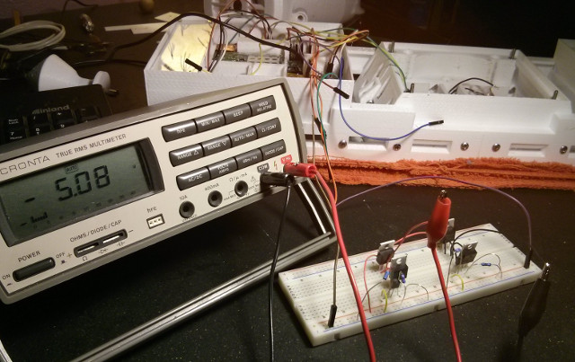
However, I don't have an oscilloscope and cannot confirm what is exactly occurring in real-world use, but during initial testing, the H-Bridge seems to be working well, and it allows me to use PWM and change the polarity rapidly.
The circuit barely fits inside the space I allotted in the screwdriver housing, and I refrained from using hot-glue in this case to prevent the MOSFETs from melting the glue which could cause it to drip into the motor mechanism. The holes on the side of the housing conveniently allow the wires to pass through it.
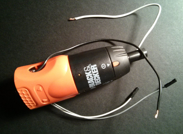
PWM Speed Control for Orbital Mechanics
While TRILLSAT-1 doesn't orbit a heavenly body on its own like a "real" spacecraft, the Planetary Mass does indeed orbit the central craft under changing gravitational conditions, which fits well under the definition of orbital mechanics, but the conditions are slightly different. So its a different kind of orbital mechanics, as the physics are related, but slightly different.
The Capstan is analogous to a central body, such as the earth, which exerts a force on the orbiting satellite, which could be thought of as a moon, but not the same kind of force. The Planetary Rod does constrain the moon to a circular orbit (a special case of the elliptical orbit), but this orbit exerts a varying force on the mass due to the angles and position of the mass and the entire craft. But our real earth that exists on the ground beneath this mechanism exerts a real gravitational pull that could be thought of as the Sun, vastly larger than the two bodies doing their dance above.
Our Sun, like our earth, does not have a homogeneous density, so the gravitational forces on the orbiting planetary system vary during its orbit. That's just what happens in this craft, as the mass orbits the craft, it speeds up and slows down, causing the motor to draw current irregularly from the batteries. In some cases the heavy mass is up high above the tether, then it begins to lower with gravity-assist, then it raises again, but not as far, since the tether is sloped.
Then it does the same thing in reverse on its second half, it begins to go down at a gradual slope into a valley, then performs a very steep climb to the top. And remember, the Capstan isn't just driving that Planetary Mass, it could also be lifting the entire craft up that slope at the same time. In these cases, the current is at maximum.
Now, if we reverse the motor polarity, the entire sequence is reversed, with a caveat--the craft is now sliding down the slope, adding energy to the assist the mass.
This would be analogous to orbiting the real sun or earth in a circular orbit if the densities were exaggerated, if we were to pass over giant mountains that tried to pull the craft to a lower orbit, but we had to engage the thrusters to compensate, to keep it circular.
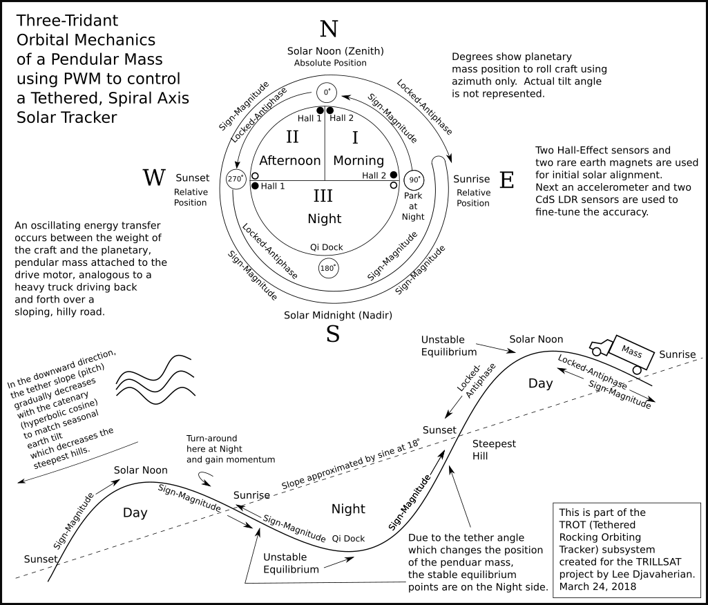
(Click diagram to enlarge)
Here is another analogy: You could think of it like a truck carrying a heavy load on cruise control traveling a hilly road at different speeds. In these cases, in order to maintain a constant speed, the driver has to foresee the conditions and manually increase the speed before the hill approaches to allow enough horsepower to be present when needed. But, since our "road" is fixed and predictable and we know its rough position (we can even get a more precise position if we include the accelerometer and CdS/LDR data) then we can create an algorithm to do this automatically.
I didn't really pay much attention to this relationship until I fully built the craft and drove it under load, and then it became clear that I couldn't just use simple PWM speed control routines, as the mass was causing the motor to stall in some places or whipping around too fast in others, heating up the motor, stressing the frame, and destabilizing the balance.
Luckily, I had the foresight to implement a PWM (Pulse-Width Modulation) control to a fairly powerful MOSFET H-Bridge, which allows a duty cycle of less than 100% that reduces the current to the motor, and can be programmatically changed on-the-fly. I knew that slow starts and stops would be needed to prevent jerking to avoid tether sway, but I never expected that I would have to traverse mountainous roads...
PWM complicates programming significantly, but it doesn't require any additional parts. MOSFETs have more capacitance than some other types of transistors, which limits their max frequency somewhat, but they are still well within an effective range for this type of motor drive.
There are 4 distinct quadrants in 2 directions (8 unique phases) that need to be considered when driving the motor:
** Upward craft motion
* Upward planetary swing to apex (hardest to start)
* Upward planetary swing to midpoint (easiest to stop)
* Downward planetary swing to midpoint (planet assists craft motion, hard start, normal stop)
* Downward planetary swing to bottom (planet assists craft motion, normal start, easy stop)
** Downward craft motion
* Upward planetary swing to apex (craft assists planet motion, normal start, hard stop)
* Upward planetary swing to midpoint (craft assists planet motion, normal start, easy stop)
* Downward planetary swing to midpoint (hardest to stop)
* Downward planetary swing to bottom (easiest to start)
Each phase is unique and requires different start and stopping torque and speeds. The first one is the most critical, as the craft requires maximum torque to get moving, having a higher static torque requirement than dynamic (once you get it moving). I had decided, early on, to add 2 Hall-effect sensors and 2 magnets to track 3 "tridants" (mentioned later). I knew that the panel would have to tilt from sunrise, to solar noon, to sunset, and then repeat. So I needed positive confirmation on those 3 positions: sunrise/sunset are relative positions, and solar noon is absolute.
Again, it was a very lucky thing that those 3 tridants are all I need for controlling the orbit. I use the word "tridant", even though there is no such word, since I'm splitting up a circle into 3 irregular quadrants, but they really aren't quadrants at all.
By considering "solar noon" to be the planetary mass stationed directly below the Radio Box pointing to the North, just like North on an analog compass, the planetary rod sits at an elevated angle to the ground. This angle reduces the vertical torque on the rod, keeping it from bending, unlike the opposite end of the craft, where it is almost horizontal. It's like it is resting at the top of the tallest hill, in unstable equilibrium, with the highest energy/lowest entropy state.
The positions can be labeled as a compass face for ease of reference, with due East (Sunrise) being 90 degrees and due North (Solar Noon) being 0 degrees, and due West (Sunset) being 270 degrees.
I was able to re-capture some of the energy in the craft and Planetary Mass to use it for "gravity assist", analogous to a real spacecraft, as the downward weight of the craft helped to lift the heavy mass from sunrise to noon, for example.
So here's how I decided to drive through the 3 tridants (Morning, Afternoon, and Night):
- At sunrise, 90 degrees, the planetary mass is parked to the East, tilting the panels to the eastern sky. There is a stable equilibrium point somewhere past 90 degrees, maybe 110 degrees or so, so the mass would seem to fall towards it, but the gearbox resists some of the force and it is also held up by the downward, opposing force of the entire craft sliding down the tether.
- It then swings upward to solar noon, 0 degrees, to the unstable equilibrium, requiring energy, but not that much, since the craft is still providing "gravity assist" to the mass.
- By sunset, it has swung to the West, but in this case, its like that heavy truck going down the steepest hill, it has to slowly brake to 270 degrees, and it doesn't like to stay there, since the weight of the craft is still pushing it. It is only held in place by tether friction and the gearbox at this point. Note however, that as the mass lowers, it really lowers and tilts into that "valley" as the entire craft tilts. It doesn't have to remain at 270 degrees long, however, just until sundown, and then it doesn't matter if if slips further into that valley, since the long night follows. In fact, its actually good if it does slip, since there are no Hall-effect sensors in the night region that could "blind" Sawyer from receiving haptic Morse messages from Huckleberry over the MISO line if the haptic Morse communication system is used.
- The final phase, after sundown, is to engage the motor counterclockwise and use the downward energy to pass through the large lower Night tridant all at once, through the valleys and hills until it passes 90 degrees on the counterclockwise upward swing. But it can't stop there, since the craft is now down the tether one revolution, so it then reverses direction, clockwise, and goes back to where it came from, 270 degrees, but doesn't stop, since this is the steepest hill, so it uses its momentum to lift both the craft and the planetary mass up to noon, 0 degrees, then it slows down again and parks itself where it started, at 90 degrees, waiting for the sunrise.
So it really is a form of orbital mechanics, but I'm not a GNC Engineer↗ and am nowhere skilled enough to make such complicated calculations. But even such engineers cannot mathematically solve certain problems, so they have to model/approximate it instead. The famous Three-Body Problem, for example, has no known algebraic solution, and that is just a mere 3 bodies, imagine 4 or more.
It reminds me of my childhood home. We lived near the bottom of a valley where 3 roads met, uphill on all sides. When guests had to drive away during in the snowy winter, they would sometimes get stuck and have to use this method. I remember watching my dad's friend rock back and forth in a big, 1970's sedan, shifting between forward and reverse in the valley until he built up enough momentum to make it up and over the hill.
However, driving the craft turned out to be very difficult and I later had to add the Delta-v Drive System.
The PWM that can produce nice, slow starts also needs to stop that mass when it is parking itself "downhill", such as that sunset location of 270 degrees. So it needs to have brakes.
So I programmed two different types of PWM that can assist with these varying conditions and add those brakes, Sign-Magnitude and Locked-Antiphase.
Sign-Magnitude and Locked-Antiphase Drive
Due to my two-input H-Bridge design, the motor cannot "coast" and is either constantly powered (locked-antiphase) or in a coasting mode (sign-magnitude with rheostatic braking). I really don't need free coasting which would allow the planetary pod to slip, so this H-Bridge was ideal. This design simplified the wiring, simplified the PWM control, and prevented any software shoot-throughs from occurring.
Sign-Magnitude could be thought of as that truck as coasting and hitting its brakes when going down a steep hill. It uses less power, but is harder to stop.
However, the constantly-powered Locked-Antiphase drive is much stronger than rheostatic braking (is a type of active braking) that pulses the motor in forward and reverse in quick succession, like a strong hand "holding" it, turning it at various speeds. It can even hold it static, not moving, using no power whatsoever, due to an odd phenomenon, unless a force is applied. But in normal use, Locked-Antiphase is less efficient and puts more strain on the motor. It also has half the PWM resolution of Sign-Magnitude.
So Locked-Antiphase could be thought of as that truck downshifting to a lower gear and using its brakes when going down a steep hill. It metaphorically uses more power since the RPMs go up, but is easier to stop. (Note, however that modern computer-contolled engines and electric cars with regenerative braking can now account and correct for this).
So in cases where pure acceleration torque is needed (an upward drive against gravity), Sign-Magnitude is ideal, and downward, when it has to slow to a brake with gravity, Locked-Antiphase is ideal, and these two drive modes are interchanged when driving the Planetary Space Pod in its circular orbit.
During my testing, however, the PWM torque drops off at slow "speeds" (duty cycles) when I need it the most on startups, so I may try adding a brief, initial boost or experiment with PFM (Pulse-Frequency Modulation) or sine wave modulation at slow speeds in the future.
Rheostatic Dynamic Braking
Since I have full control over the H-Bridge, as is done during pulses of Sign-Magnitude drive, turning off the motor immediately cuts power by shorting the 2 motor leads due to the design of this particular two-input bridge. It allows the motor to quickly come to a stop without using any current from the battery. This is due to the fact that DC motors are also generators, and the current they generate can be redirected back into itself to counteract this rotation. I'm not actually using a rheostat, but the Drain-to-Source resistance of the MOSFETs is low enough to pass 62 amps, acting similarly by turning the excess energy into waste heat.
Dynamic braking is very useful in my case, since, the alternative, reverse-current braking, or "plugging", at a high speed by quickly reversing the polarity of the motor creates large current spikes that could reset the CPUs. I have some large capacitors on the power lines that can handle smaller spikes, but the big ones could get through. This is essentially what is happening between the pulses of Locked-Antiphase drive, but it's not as severe, since the unit is not doing a full reverse at high speed, but a partial one at lower speeds.
Hall-Effect Rotary Encoding for Closed Loop Control
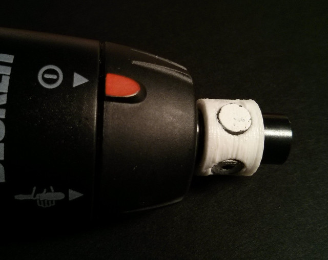
To obtain orbital position information from the Capstan tridants, as mentioned above, I placed 2 small headset speaker magnets on the capstan and used two Hall-effect switch sensors (digital sensors, not analog like the ones on the BLDC) to detect its proximity. Both the sensors and the magnets are offset by 90 degrees.
I wanted to obtain positive feedback about the motor position of the solar panel at standard orientation solar noon, and there is only one position where both Hall-effect sensors are activated, but this leaves one tridant boundary, Solar Midnight, the nadir, unknown, which is an acceptable trade-off, since the solar panels don't care when midnight occurs.
The Hall-effect sensors also allow computing positive travel distance along the rope, detecting motor failure, providing redundancy for the accelerometer, but they later turned out to be critical for correcting the dead-reckoning zones in the Delta-v orbital mechanics drive system and acting as day/night trigger points for flow-control of motor torque value streaming over I2C. For there is no other form of linear distance measurement on the craft, critical to the equations.
They are very crude sensors with extremely high tolerance in my setup (about 50-55 degree error for each sensor position, 15% of the total orbit, 45% for all three "sectors"). The error is so large that the sectors are like 6 pizza slices on the orbital period. So you actually pass through the tolerance zone itself when you are inside the triggered sensor (as the magnetic field is still being detected).
But as a fascinating benefit, that slice of pizza, that sector helps to further subdivide my three tridants, actually increasing overall precision versus using a more precise sensor. Because the edge detection is precise along the edges of that pizza slice, I can determine where the motor shaft is positioned within 6 sectors instead of just 3 and accurately know the angle at the edge. Technically, there are actually 8 sectors since there are two small slivers around solar noon before the two sensors are completely disengaged (additional error in how I mounted the sensors and magnets), but this is treated as switch bouncing and ignored.
This was hard to calibrate, though, as it changes depending on motor direction and mechanical slack, so I had to carefully measure the error in both directions with a protractor at all of the sensor trigger points, and also measure the mechanical slack to offset that angle, which changes on direction but stays constant once it is moving. Later I found that my manual measurements were still not precise enough, so I created an auto-calibration system to have the craft find these values itself since the motor speed at a fixed current along with the CPU timer, stays very constant, and precise angular distances can then be calculated using the "distance = speed x time" relationship.
This reading can also substitute for the values obtained by the accelerometer in very windy situations, but it only measures 6 zones (East Sunrise, Morning, Solar Noon, Afternoon, West Sunset, and Night). Morning, Afternoon, and Night are "in-between" zones when no Hall-effect sensors are triggered, and because they are indeterminate, they are only deduced by rotational motion, which changes on direction. But due to the peculiar interlacing of the determinate and indeterminate zones, switch bouncing was an issue and so a dynamic debouncing algorithm had to be created. The zones vary in size at about a 1:2:6 ratio, Morning and Afteroon being the smallest, Sunrise and Sunset, being twice as large, and the Night zone being about 3 times larger than that, and this size variation provides some important information for the debouncing system.
It also also allows the ESP8266 and/or Sawyer to take over in an emergency when the Pi Zero W is powered down (along with its accelerometer algorithms) to drive or orient the panels. In the daytime, information from the CdS LDRs and Huckleberry can also be incorporated.
By having separate sensors on the panel and the motor, a stuck rope (ice, for example) can also be deduced.
Ideally, I could use a pure, analog Hall-effect device (without the built-in binary logic) to monitor the magnet position over the entire orbit, as the Hall-effect is an analog signal, but this would require more experimentation to get the voltage in the range of an ADC, and I don't know how the motor PWM might affect it. With the accelerometer, CdS LDRs, and motor PWM, I have enough methods to obtain the accuracy needed.
Passive Mass Damper
For a few months, I studied tuned mass dampers↗, and they are fascinating but require careful tuning. These are used in both tall buildings and bridges, for example. I've seen ones that use pendulums, springs, rolling balls, and viscous fluids.
I thought about adding a tuned liquid column damper to the main gondola unit, a U-shaped chamber filled with glycerol around the axis of the tether, but that would have added needless weight to the craft. But since I was already adding weight to the Planetary Mass/Space Pod, I thought about it again.
Inside the fully-closed, Planetary Mass sphere is another sphere at the top, and a cone at the bottom. The cone is mainly to aid in printing the top of the hollow sphere to prevent it from collapsing, but the whole thing is filled with enough steel BBs to weigh 458 grams (about 1 lb), with some space left over so the balls can roll around. When the Planetary Mass moves to the side to tilt the craft, the balls roll away from the cone and inside the spherical portion, allowing the tiny steel BBs to roll as a 3-degree of freedom, rolling ball damper. I could have used a concentration of (70%) glycerol, as it is non-toxic, has a density higher than water, doesn't freeze until it gets near -40 degrees Fahrenheit, and has a viscosity higher than olive oil. (Interestingly, higher concentrations raise the freezing point rather than lowering it further. It used to be used as automotive antifreeze, before the toxic varieties replaced it.) But the liquid was not heavy enough in my final design, and I wasn't about to use liquid mercury, so I used the steel balls. I once accidentally broke my family's old rubber dead-blow mallet when hammering a drain pipe, and round steel shot flew all over the floor, as some of them are filled with tiny balls to assist in damping the blow to prevent rebound. I confirmed mine was steel and not lead. The balls could serve such a purpose (perhaps if it hit a branch or tree), but it probably isn't much use in the wind, and is obviously not tuned. But they do help to absorb shock from the screwdriver's planetary gear when the Planetary Mass is quickly started and stopped (parking on the Hall-effect positions, for example). But this can also interfere with the active damping system.
MEMS 3-Axis Accelerometer
While the CdS LDRs can detect solar position, and the motor can be driven for certain time periods for approximate panel tilt angles, I decided that some sort of tilt sensor should also be added for additional confirmation, and to detect windy conditions.
The cost of tiny MEMS sensors has dropped significantly, and a board containing an LIS3DH was available for only $4.95. Gyros and IMU boards can now be found for around $10, but I wanted to keep the cost as low as possible. It uses an I2C interface, and the trigonometry computations can get complex, so I used the math functions of Python on the Raspberry Pi rather than use up the precious memory of NodeMCU on the ESP8266.
This is my first experience with any MEMS sensor, and today these are popular in robotics and quadcopters, and smartphone app developers are very familiar with their characteristics, as many apps have to manipulate the raw motion data. I had always wanted to build an inverted pendulum balancing robot, and this gradually eases me into these concepts, being a real pendulum and inherently stable.
Originally I decided not to use one and to disassemble an optical mouse and use it to track position of a wide, hanging pendulum that I placed inside one of my circuit boxes. Optical mice are very inexpensive, relatively low power, and contain neat tiny cameras in them that track surfaces. In this way, the optical mouse is acting as a 1-axis accelerometer. They could also do 2 axes, but you have to be careful to avoid pendulum rotation since the mouse only handles translation well. But the main problems were that I would need to add a USB hub, since the Pi Zero W only contains 1 USB port, already consumed by the audio card, so the cost and power of this setup is actually greater than a high-tech 3-axis accelerometer. A Bluetooth mouse on the Pi Zero W is another option, but again, this adds cost and power. Also, the pendulum would be subject to translational forces on the rope, just like a real accelerometer.
The LIS3DH accelerometer only responds to linear, not rotational forces, like a gyroscope would. Since the entire craft exhibits tangential rotation around the rope, this becomes more difficult. It works well, however, for determining vertical orientation when stationary (due to gravity), and through trigonometry, it can also calculate rotational displacement such as roll and pitch. But yaw, sway and vibration in the rope (wind or motor movement) alter these vectors which can fool the algorithm into thinking rotation is occurring when it is not. Gyroscopes used as sensors are immune to this, but gyroscopes don't measure rotational displacement (which would have to be calculated) and don't measure displacement from vertical. Accelerometers that measure rotational displacement, in addition to getting noise from rope sway and vibration, would also measure centripetal force, further confusing any simple algorithm.
But a single, cheap 3-axis accelerometer provides me with more data than a gyroscope would, it is just that this data is more difficult to interpret. I consider this a good trade-off--as I improve my algorithms over time, I can improve the operation without adding extra hardware. This is kind of like the designs of real spacecraft--build them with a lot of options, combinations, and data, and let the scientists and engineers figure out over the years what to do with it back on earth.
I mounted the accelerometer flat and inverted (Z-axis vertical), and since the unit is tilted along the rope, both the Y and Z axis are affected by gravity when the panel is level. No rotation against the rope can directly be measured, but forces may be detected. This is good, since I don't need to measure this rotation which briefly occurs when the motor is engaged.
A benefit is that if the Y-axis pitch changes drastically, or if X, Y, Z drop to zero, the rope has been broken, which can quickly signal an alarm, through the piezo element, before it hits the ground. The chip also has a built-in free-fall interrupt, which can power up a sleeping ESP8266 (indirectly, since Huckleberry monitors the interrupt line) and allow it to send out an alarm.
The accelerometer has many other uses, too, and another experiment is to use it for haptic Morse Code communication, which I call "Tethered Haptics Using Morse Pulses".
Active Pendulum Damping System
Using a single rope has a major limitation in that the tangential forces (the East-West direction around the rope) cannot be stabilized other than via gravity, inertia, a mass damper, or friction of the pendulum, and strong winds will always affect it. However, because the Planetary Mass controlled by the motor can also affect these forces, I decided to explore an experimental active damping system, creating an equal and opposite force to nullify or at least damp the oscillations.
Robotics engineers have already solved the inverted pendulum problem, and with modern sensors and microcontrollers, a person can build a robot that balances on only 2 wheels or even a sphere. It is still fairly difficult to do.
In my case, I have both a normal pendulum (the craft itself) and an inverted pendulum (the Planetary Mass in some orientations). Normal pendulums are inherently stable and gravity and friction will always return them to an equilibrium. I don't have to worry about the whole thing tipping over. But there are points in its the Planetary Mass orbit that are in unstable equilibrium.
In theory, when the accelerometer detects unwanted rotation, the motor can be pulsed in the opposite direction, the width of the pulses (PWM) being proportional to the magnitude of the swing. The heavy Planetary Mass then jerks the entire craft to counteract the swing, with some of the shock being absorbed by the passive mass damper balls inside the Planetary Mass sphere.
However, this jerk creates all kinds of unwanted forces: rotational, centripetal, rope vibrations, ball damper shifts, which are hard to mathematically analyze using only accelerometer data. It is in a highly hypothetical, experimental state, and there are some huge computational problems to overcome. But it is a fascinating experiment, nonetheless.
Some of the big issues are:
- Quick motor start-up and quick reverse, which is necessary to create the large torque pulses needed, uses a large amount of current.
- It is difficult to compensate for the effects of wind, friction, the damping of passive balls, and the forces acting on the fast-moving Planetary Mass during different points in its orbit, which can make accurate calculations impractical.
- The pulses require bursts of battery power and the wind is erratic. It is unknown if the energy saved by damping the panels is more than the power consumed by the damper.
- Obtaining actionable data from the accelerometer will be difficult.
BLDC Gyroscopic Stabilization and Reaction Wheel
Today many people use tiny MEMS gyros as sensors, but gyroscopes are also very interesting actuators if they are large enough. So I placed a small, high-speed BLDC motor along the rope axis, attached to 3D printed flywheel.
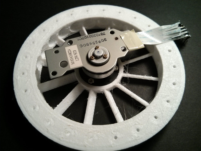
When turned on, it creates a gyroscopic inertia which resists any attempts to rotate it, damping high wind. This is experimental and consumes a lot of power, but it seemed so simple and inexpensive at the time, that I had to try it. Gyros are used as film/video camera stabilizers and large versions are used at sea to stabilize ships in high waves. Helicopter blades, in addition to providing lift, are also inertial gyroscopes which damp roll and pitch, exactly what I am trying to do (especially roll). There are interesting effects like precession against the rope that occurs when torque is applied.
Spacecraft also use such flywheels as reaction wheels for attitude control. Similar to the active damping mentioned above, because the wheel is along the same axis as the Planetary Mass drive motor, it could be pulsed in the opposite direction at the same time the drive motor is engaged, counter-rotating and canceling out some of the unwanted start-up twisting torque, a form of reaction control.
I decided to use the motor from an old Lite-On LDW-411S DVD burner manufactured in 2003, with number M3B912 printed on the board.
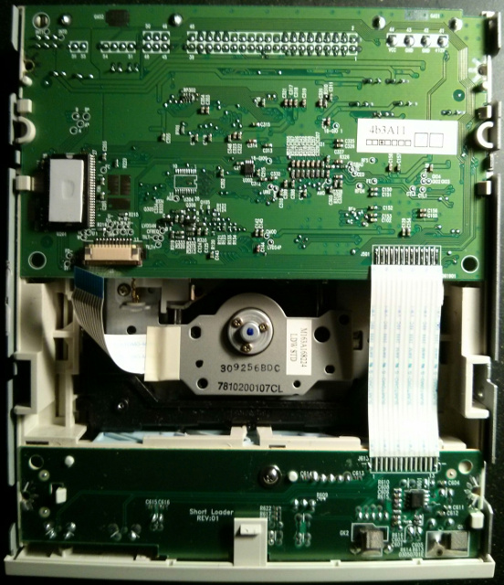
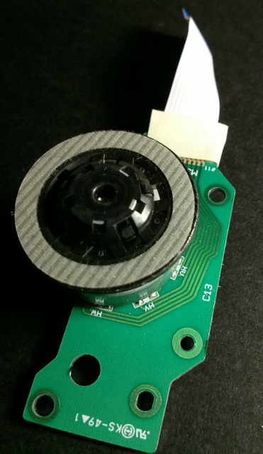
DVD motors are ideal being highly efficient, lightweight and designed for spinning lightweight discs at high speed, and coincidentally, the 120 mm diameter of a DVD barely fits under the width of the solar panel. This drive was rated at 52x CD speed and is probably a CAV (Constant Angular Velocity) drive which can hit at least 10,000 RPM with low RF interference. It also provided its own high-speed bearings which I didn't have to install. Model airplane hobbyists have even used such motors to drive propellers, since they are fast and lightweight. They can provide more torque that you would expect due to the strong rare earth magnets.
This is a 3-phase BLDC (brushless DC) motor with 3 Hall-effect sensors, common in modern DVD drives, a fascinating motor design doesn't use brushes but instead relies on a computer to switch the circuit--it doesn't needed any brushes to touch the commutator to complete a circuit. The 9-coil stator is stationary and only the rotor with magnet spins as the stator creates a rotating magnetic field which drags the magnets along with it. I think it is a "delta" design, but I'm not certain.
It is similar to a stepper motor but much lighter and was designed for smooth and fast rotation, not maximum stationary holding torque. But they have a major downside--driving them is very complex. I mean very complex...
If I would have known how difficult it was to get the BLDC motor working before I started, I wouldn't have added it but would have chosen a simple brushed motor instead. But I'm glad I stuck with it and learned more about them. I needed 6 MOSFETs to switch the stator coils on and off in the right pattern. This requires 9 IO lines, since I also need to read those 3 Hall-effect sensors. There is a way to skip the Hall-effect sensor and read the back EMF on the unused coil, but this is even more complicated. So I incorporated an ATtiny 1634 microcontroller, Sawyer, to handle the motor, and as I am very familiar with programming it.
Due to the difficulty of creating the H-Bridge for my capstan drive, a much simpler circuit, I decided to use an L6234 3-phase driver IC (containing its own MOSFETs instead)... but then I found out that the driver IC required a high voltage to drive its own MOSFETs and had to add extra circuitry for its charge pump booster. Another issue is that, if you power logic inputs before you power up the chip, you can burn out your inputs, damaging the microcontroller.
The experimental Gyro is not perfect, but it is "good enough" to test the concept.
Both of my motor systems were nightmarishly difficult, in both hardware and software, and took a disproportionate amount of time to create, compared to other subsystems in the craft. In essence, I ended up building/programming my own ESCs, electronic speed controllers↗, from scratch. I could probably build a quadcopter now with some of the knowledge I've gained. (The BLDC motor itself isn't difficult to construct by the way, and model airplane hobbyists have rewound their stator coils to increase their power.)
I couldn't even install the Gyrofan flywheel or close up the case until the gyro programming was done since I couldn't be sure if the wheel would stall and burn out the motor or whether it would run too fast and disintegrate. In earlier testing, it locked up my I2C interrupts preventing me from shutting it down, or it sometimes paused on a step forever since the PWM interrupt was itself, interrupted. In many cases, I had to quickly yank the 5 volt power from Sawyer to stop it, making sure I didn't yank the 7.4 volt motor power (which would cause Sawyer to short out through the powered-off L6234 controller).
I've tested the Gyrofan at 360 RPM with a fully loaded mass on the tether, but it doesn't perform much stabilization. Later, I was able to successfully ramp it up 5 times higher to 1800 RPM on a table but haven't yet put it on the tether at that speed to check for any stabilizing effect.
Comparators Revisited
And if that wasn't enough, the BLDC Hall-effect sensors are real, analog sensors, producing AC signals, and so I had to add comparators to find the exact cross-over points to convert to digital signals. Nine IO lines, 3 chips, a bunch of resistors and capacitors, all crammed into a small space, along with a lot of programming just to turn a motor! I think I picked the most complicated consumer motor that I could have driven...
You have to commutate it in a sequence of 6 steps for each direction, 36 steps for 1 revolution, and to control speed you have to use PWM on each step to chop up the voltage even further. This required very fast timing intervals so I had to use the hardware 8-bit timer on Sawyer (since the 16 bit timer was already used by the H-Bridge). Luckily the hardware timer Fast PWM can be configured internally since I was using the timer pins for CdS LDR inputs (and it won't affect the pin unless it is set as an output), and I was able to trigger interrupts on the high/low phases of the PWM signal which in turn triggered different pins. ATtiny microcontrollers are wonderfully configurable like this, a tiny, switching microcosm of the craft itself, in a way. At first, I had a bad solder joint on one of the three coils and was surprised that it ran on only 2 coils, although the torque was low and it sometimes stalled on startup. With all 3 coils working, it ran so fast it threw a bolt across the room before I could turn it off...
But when a BLDC works, it's cool.
Technically you can drive such motors in open-loop PMSM (Permanent Magnet Synchronous Motor) mode without any feedback, but you have to speed it up slowly and it has poor torque and slow reaction, which removes the reason for it in the first place. I need it to hold gyroscopic position and react to forces--it has to be strong and fast and efficient, where BLDCs excel. The Hall-effect sensors, while a hassle to connect to the comparator and monitor have the wonderful benefit of providing angular velocity feedback which I can compare to the ATtiny's hardware timer to obtain RPM. Then using a closed-loop algorithm, I can tell the motor to maintain a certain velocity (pumping more or less current into the stator to hold this velocity). I can put my finger on it, for example, and hear it increasing its energy to maintain its speed. This allows a more stable gyroscope as it can better compensate for external forces to maintain its position in space.
On a side note, in 2017, my brother and I repaired a GE washing machine, and I was surprised to see that it had no transmission (a "hydrowave" model) but also relied on a 3-phase BLDC motor which was computer-controlled with a Hall-effect sensor. These things are wonderful motors when they work properly. But when the mechanical tub shaft failed during a high-speed spin, it also strangely burned out the motor board, which I assume was due to some kind of cascade effect (like the opposite of what occurs when failed spark plug wires in a car cause engine damage due to misfires that lead to the firing of the wrong cylinder on the subsequent rotation). We had to replace both the shaft and the motor (since the control board was on the motor and not sold separately) but it works well.
And as luck would have it, about a week before publishing this page, I burned out the first TRILLSAT-1 BLDC when another cascade failure caused the motor to stall before I could shut it down quickly enough. I had failed to turn on the ATtiny's brown-out detection and the intermittent on-of-on solar power caused them to lock up, which allowed the MOSFETs to turn on (since the ATtinys were no longer in their default pin states) turning on the power and stalling the motor. Since the ATtiny was locked up, it couldn't sense the stall and shut it down. I have since replaced the motor and turned on brown-out detection on the ATtinys.
BLDC's are also used in electric automobiles and spacecraft due to their advantages. Rocket Lab, for example, recently 3D-printed their Rutherford rocket engine↗ and used battery-powered BLDC motors to pump the fuel into the combustion chamber, a very different design approach from previous engines.
Instead of using a polycarbonate DVD, I decided to 3D print a PETG disk at around the same size to allow me to put a ring of 1/4 inch steel slingshot "shot" around the edges. It looks a little bit like a ship captains wheel or a water wheel.
Keeping the weight at the outside edges increases stabilizing torque, and so does the rotational velocity, as it is related to momentum (mass times velocity) which is directly related to kinetic energy, that wonderful mysterious thing that we can only measure indirectly. But I don't want to add weight to the craft as it is hanging on a rope, which is why I added as little weight as possible but spun the gyro very fast. I can't spin it too fast or even get close to the BLDC max speed or the disc will break apart due to the tremendous centripetal force.
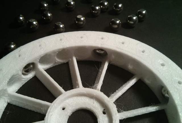
I thought about allowing the balls to spin freely in their sockets, like a ball bearing cage, and then allow the balls to roll on an outside race, but this would require additional design and testing (and would be very noisy).
PETG has pretty good tensile strength, almost as much as polycarbonate, and it has a slightly better elasticity. Printing the disc flat also meant that layer strength is not an issue, only pure tensile strength. While it only costs a few dollars to add the extra microcontroller and MOSFETs, the biggest drawbacks of this gyro experiment is the additional weight and length it adds to the craft, the programming complexity, and it is not ideal to have a high-speed spinning wheel near Lithium-ion batteries (which is why I designed an aluminum Battery Cover acts as a guard between them). At high RPM's they can break catastrophically, similar to spinning ball bearings suddenly failing on a machine or automobile, potentially turning the metal shot into projectiles, so the entire thing is enclosed in a very thick plastic Battery Frame. Ironically, they can easily develop as much FPS as an actual slingshot. Ideally, I would use the balls to also serve as ball bearings, helping to stabilize the assembly, but this is no simple task.
Also, ideally, I would scrap the entire screwdriver mechanism and build my own shorter gearbox, but it is difficult to build a high-torque system that could also drive the capstan reliably, which is why I used the battery-operated screwdriver. In my research, I also came across Kapitza's pendulum, another interesting stabilizing effect, the but the entire unit would have to be vertically vibrated, adding its own issues.
But when the BLDC gyroscopic flywheel is sealed up inside, like a true inertial phantasm, like the warp drive from the bridge of the Star Trek USS Enterprise NCC-1701, I can no longer see it or access it, but only hear it and feel its effect.
UV, Wind, Rain, Hail, Ice, and Snow
The TrillSat, containing only one drive motor, has only one option to avoid bad weather: energize the motor to traverse the rope and tilt the solar panels which also generates an initial angular force. So much to do with so little.
Ideally, it would be nice to know ahead of time what the weather is like by measuring the wind (anemometer), precipitation, temperature. I've got the external temperature covered with an DS18B20+ sensor, but I decided not to add any wind or precipitation sensor but deduce the weather using the other sensors. For example:
- Rain: If the DS18B20+ in the solar panel detects a sharp decrease in temperature (but not freezing), it is probably raining. This can be corroborated by dimmed light from the CdS LDRs (if daytime) and fluctuations in the vertical accelerometer readings (although wind may interfere).
- Hail: If the accelerometer detects sharp but brief changes in the vertical direction, it could be hailing. The Gyrofan Hall-effect sensors might also trip if the gyro rotates due to the vibration. The panel temp probably won't drop as quickly as rain (as water carries heat away fast).
- Wind: If gravity has been subtracted, large lateral rolls in the accelerometer indicate that it is windy. This can be corroborated by large fluctuations in the CdS LDRs (if daytime) or the sudden tripping of the Gyrofan Hall-effect sensors when the gyro is not in use. Note that both the tilt of the panel and the position of the Planetary Mass affect its cross-sectional aerodynamic profile. The craft can be directed to land under windy conditions.
- Lightning: If the upward facing CdS LDR experiences spikes of light at night, this is probably lightning.
- Snow: In the day, the CdS LDRs may show lower light levels. A sudden roll, spike in rotation from the accelerometer, may be snow slipping off the panel. If the panel is cooler than the outside temperature in the daytime, then either snow or ice is covering the panel.
- Ice: If the temperature rise in the morning sun is lower than normal for the same amount of light detected by the CdS LDRs, then ice may be covering the panel. Because the panel is dark and angled to the sun, the ice should melt quickly and the heat in the panel will rise on a different curve. A jammed or slipping motor (confirmed by the Hall-effect sensor and accelerometer) could also indicate that ice has solidified around the mechanism.
Because the panels are dark and absorb light, they radiate some of it back out as heat. Since the panels are in a closed housing, heat begins to build up like an oven and rises up to the top of the panels. Therefore I used an aluminum backing to act like a heat sink and the heat should rise up and away from the unit. Because the panels are aligned lengthwise, their circumference is longer than it would be if they were aligned as a square, providing slightly more cooling around the edges (10 vs 8).
The 3D-printed plastic is also susceptible to UV degradation, but because the main housing lies underneath the panels (and the panels tilt around it), much of the direct sunlight shouldn't hit it.
I decided to use anti-glare acrylic sheeting to protect the solar panels. Acrylic was cheap, but it has high light transmission (around 92%). It is also a fairly lightweight plastic, and much lighter than glass. Ideally I would have used an anti-glare coating to allow more light to reach the panel, but it was cheaper to just get a glossy one with UV protection.
Wind, of course will cool it, but too much crosswind causes the unit to rock. The panels can be set to horizontal to minimize aerodynamic drag in high winds, and allow air to pass underneath them, but wind turns the panels into airfoils and if it catches them at the wrong angle, it can create quite a bit of force. The tree can also sway in the wind, so to keep correct tension on the Capstan, a spring could be added to the end of the rope.
I mentioned the active damping system, but there is an interesting passive benefit to the design. Since the panels are on top of the rope (the axis of rotation) and the main unit is below, if balanced, certain types of crosswind will hit the top and bottom in a way that cancels out any rotational force. I only made some intuitive guesses here, and, of course, the cross-sectional area would also vary depending on the orientation of the panels. However, since the cross-sectional area of the panel can vary widely from only the thin edge (horizontal) to a much larger area at maximum tilt, reaching a crosswind torque equilibrium is very likely to be within in range of this design. To confirm, I may one day test the design using a blower motor as a makeshift wind tunnel and see if there is a "perfect" orientation of the panels that nullifies the rotation. I could then tell the CPU to set the tilt to this value under windy nighttime conditions when the active damper is not used.
Rain flows downward and the unit is angled, allowing rain to flow off, and I added a lot of drip edges to the design. The drive motor hangs downward, preventing rain from entering the shaft. The panels are inset to allow water to flow away from their edge openings.
However, moisture can get into the panels, steaming up the acrylic covering and causing corrosion. It is extremely difficult to prevent this, and manufacturers sometimes seal the whole thing up to evacuate the air. In my case, I wanted to keep the panels in a box. The panels themselves are sealed, but my box isn't. I simply pushed the panels up against the acrylic and used a small amount of acetic acid free silicone caulk to bond to the aluminum sheeting. If moisture later becomes a problem, I can always drill some holes in the aluminum to keep it completely ventilated.
Hail can damage the solar panels, but acrylic is fairly strong (the Plexiglass in hockey rinks is a similar material, and it can take direct impacts from pucks), and if the panels are angled to maximum, it redirects some of the impact force.
Ice can freeze the panels and capstan in place, even forming along the rope, guides, and pulleys, preventing all movement. However, since the panels are dark, and the box is like an oven, ice will quickly melt allowing at least some solar power.
Of course, emergency docking or landing TrillSat is an option. The craft could be directed to drive up into the tree itself, taking shelter in the branches, or it could be directed to "land", with the Planetary Mass or antenna impacting the ground first. A small shelter could be set up on the ground for this situation, but this would defeat much of the purpose of creating a tree-based satellite, as one might as well keep the craft on the ground permanently and simply raise the antenna.
Snow Removal
Snow can cover solar panels blocking solar charging for days. Light snow will also melt quickly, for the same reason as ice. With deep snow, the panels can be tilted and then the motor and Planetary Mass could be pulsed back and forth, jerking the craft violently which could help to slide off the snow. During blizzards, snow often adheres to one side of road signs and not the other, so the panel could be tilted away from the wind to lessen snow from adhering.
Heatsinks, Solar Reflection, Emissivity, and the Battery Warm Box
Heat also builds up inside the housing from the Radio, ESP8266, Pi Zero, batteries, motor, and MOSFETs which is closed to prevent moisture (although there is a small ring around the screwdriver shaft that is not air-tight). This is detrimental in the summer, but beneficial in the winter.

I added an aluminum back panel to the Solar Panel Frame assembly to conduct heat away, and created an air-gap above the Circuit Boxes to allow wind to pass through. And the underside of the unit is mostly white with some reflective aluminum exposed. If the panel or batteries get too hot, the panels can be tilted away from the sun, exposing the lighter side that reflects heat, also allowing a vertical air channel for convection. The entire box was sealed with acetic acid-free silicone caulk, acting as an aluminum-safe gasket to keep out moisture.
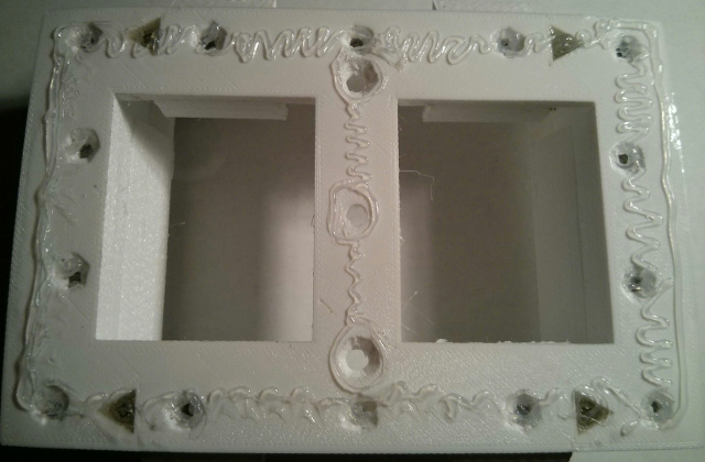
However, in the winter, the temperature in my area can get well below freezing. Most of the electronics should be fine running at cold temperatures. According to the user manual, the UV-5RA can operate from about -4 to 140 degrees Fahrenheit (-20 to 60 Celsius). This is almost certainly due to the fact that this is the discharge temperature range for Lithium-ion batteries, including the Panasonic NCR18650B cells that I am using. The IC's themselves should probably work outside of this range (although perhaps a bit out of tolerance). The ESP8266 can operate from about -40 to 257 degrees Fahrenheit (-40 to 125 Celsius) and the ATtiny 1634s can operate from about -67 to 257 degrees Fahrenheit (-55 to 125 Celsius). The CM119 IC (0 to 70 Celsius) but has a much wider storage temperature range. The main processor is somewhere around -40 to 84 Celsius, but the other components may have a more limited range.
However, typical Lithium-ion batteries, including the NCR18650B, have a rather strict limitation and cannot be charged below freezing or above 113 Fahrenheit (45 Celsius). The NASA Mars rovers Spirit and Opportunity included a insulated battery "warm box" with an electrical warmer for this reason.
The problem with building a mini warm box in an Earth temperate zone, however, is that it works against you in the hot summers, trapping the heat around the batteries. Adding a heatpump such as a Peltier device could be used to change the direction of the cooling in winter or summer (by reversing the polarity). At a maximum 2C rate of discharge, the NCR18650B could pump out around 6.7 amps per cell (and 3 in parallel would be about 20 amps). At 3.6 nominal volts per cell (perhaps less under full load), they could output around 72 watts (or 144 watts for all 6 cells combined) for around 30 minutes. There are a few 5 volt Peltier modules available within this range, but the craft's 5 volt MT3608 boost converter maxes out at around 2 amps, I do not know how well such modules would heat/cool.
So I decided to thermally isolate the batteries from the rest of the unit, not keeping them in the same air compartment as the rest of the circuitry. I was able to simply use the 3D-printing software's honeycomb infill pattern to create closed air cells in large solid PETG areas to create insulation. Note that the batteries will operate until around 140 F, although they won't last as long at those high temperatures.
I moved the batteries up against the aluminum panel which is at the back of the Battery Boxes, which collects heat. I also painted the aluminum flat black to increase its infrared "emissivity". The emissivity of unpainted aluminum is extremely low and radiates very little heat, but painted black, it turns into a radiator, emitting infrared into the battery box. I decided not to add a nichrome wire or light bulb heater, as it used precious battery power in the winter.
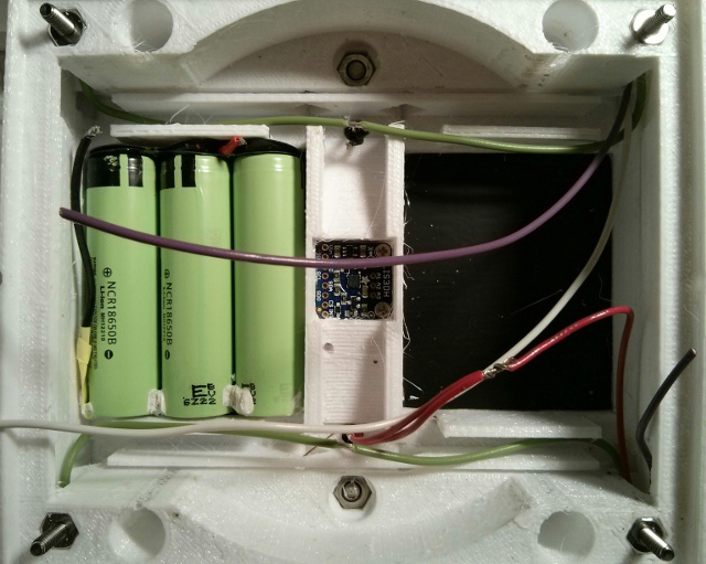
According to one test I found on the Internet by a calorimeter company, typical 18650 Lithium-ion batteries have a composite specific heat average of around .83 J/gK. Water is around 4.2 J/gK, around 5 times more than those batteries, so it shouldn't take as much energy to heat them up.
As a final backup if things get really bad, I added some small fan blades to the gyroscope flywheel under the battery so that it acts like a fan and generates up/down airflow depending on rotation direction. In the summer, the fan can be directed downward away from the batteries and panel, and in the winter the gyro motor (or the screwdriver motor) can be intentionally stalled for short periods to heat up the windings, and the fan can be directed upward to bring the heat to the battery (or not run the fan at all and allow natural convection). I haven't yet drilled any ventilation holes into the Gondola housing, but may do so in future testing.
A fascinating thing about electrical resistance heating is that, although it is inefficient if the electricity is produced from an inefficient conversion such as fossil fuels (or even a solar panel), it is 100% efficient when you turn it on, regardless of the type of heater. Any time wires do nothing but heat up, the heat output is the same. So using motors as heaters is as good a heater as any (although it can damage the motor if not careful).
Light, Sound, and Vibration
LCD Display
Since the flashlight and optional camera are recessed beneath a small acrylic panel on the underside, there is also room to fit the top edge of the UV-5RA, exposing the illuminated LCD screen from the underside. The alphanumeric display can be used to communicate error codes and other information by rewriting the radio's flash memory, which is especially useful if no desktop client or smartphone is available to communicate with it.
LED Spotlight
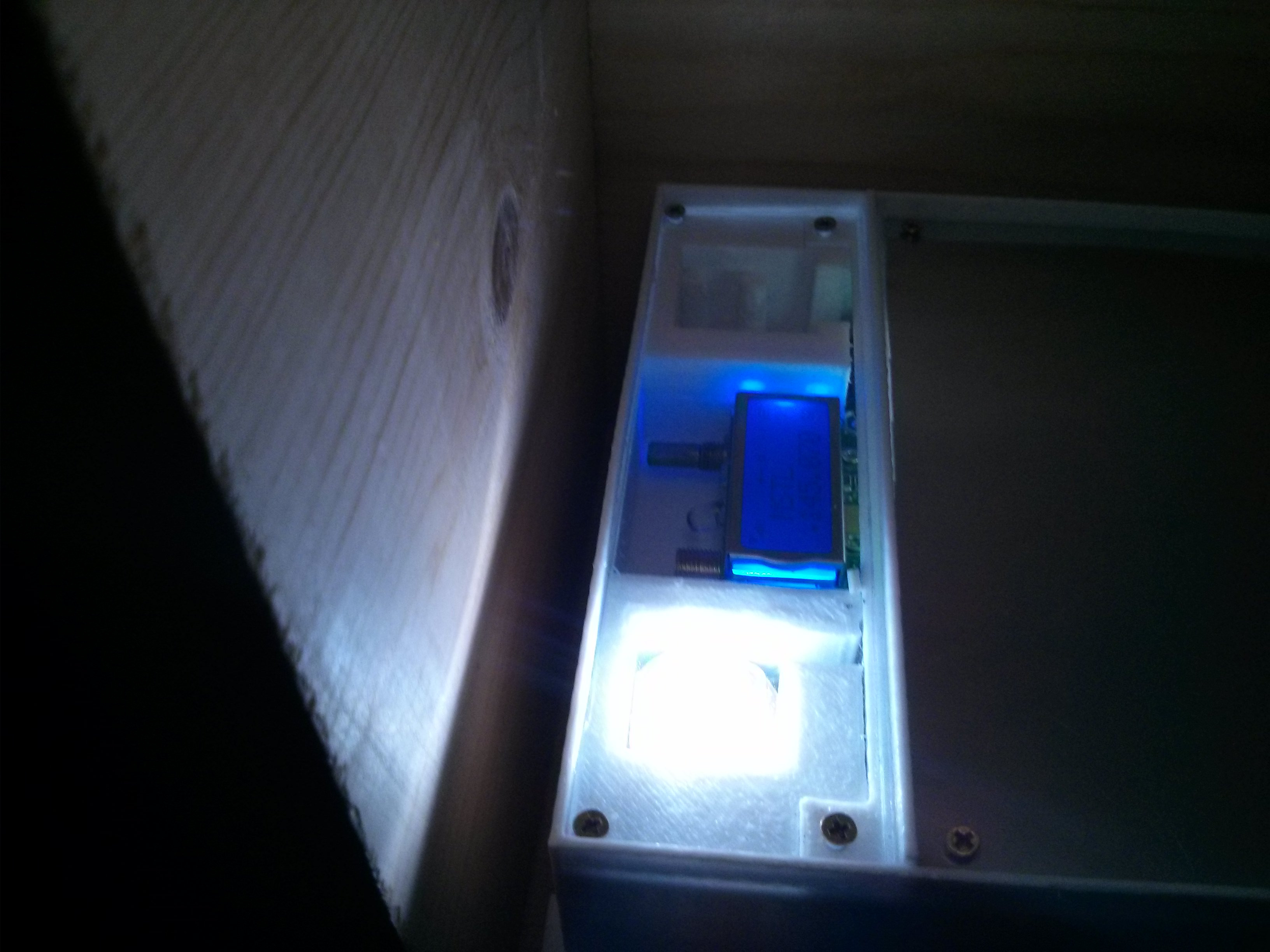
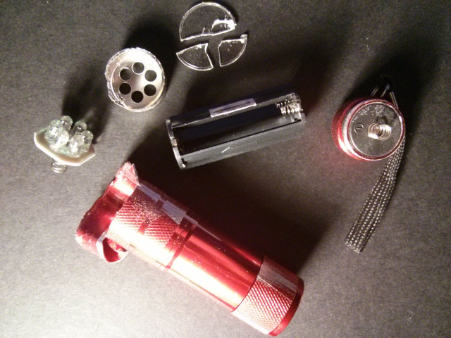
White LEDs from a cheap aluminum LED flashlight from a dollar store (like the British pound shops) were mounted beneath the same acrylic panel. A mirror on the Planetary Mass could be used to reflect the beam at different angles if needed.
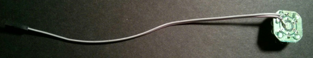
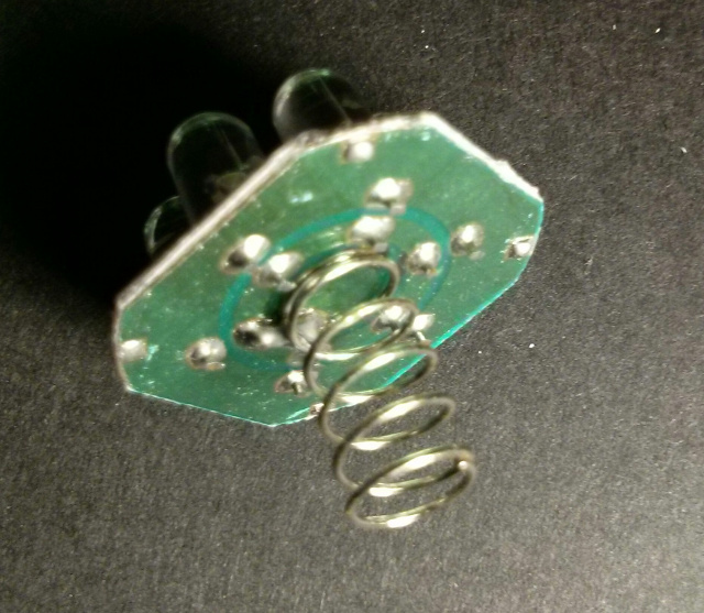
The LEDs can act as a lower-power indicator light (since powering up the radio along with its illuminated LCD display uses a lot of current). The LEDs can be pulsed (blinked) to draw very low current even though there are several of them. They are all wired in parallel, originally running off 3 AAA batteries, so I used my multimeter to measure current but had to make some rough guesses as to how much current they were really supposed to draw and settled on a higher wattage 13-ohm series resistor.
After a year of use, however, a cascade failure began occurring due to their parallel arrangement, the fact that I used it more than expected, and the fact that I may have exceeded the power dissipation of the board by running it at slightly over 5v instead of 4.5 nominal for the original 3 AAA batteries. By December 2020, the last (6th) LED of my first board finally burned out, leaving the whole board dark; it hung on a surprisingly long time given the fact that it was receiving all of that excess current.
I could no longer find the hexagonal 6-LED boards that I originally used, and the newer flashlights available in 2020 used COB, or "Component On Board" design where 5 surface-mount blue LEDs are mounted to a PCB, and a layer of silicone containing a yellow phosphor converts the light to a relatively uniform white light. I ordered a 4-pack online for about $5 so that I had some replacements in case the same thing happened later.

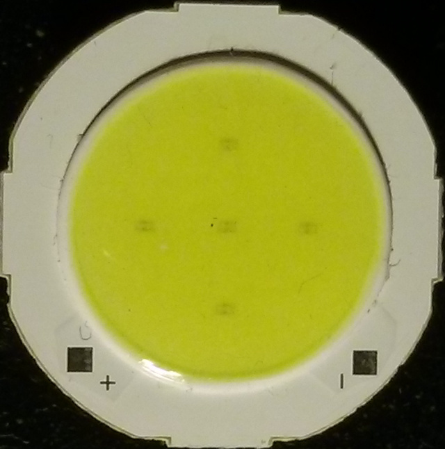
The board is a little too big to fit in TRILLSAT-1's housing, but when I carefully cut the edges of the PCB, it fit nicely.
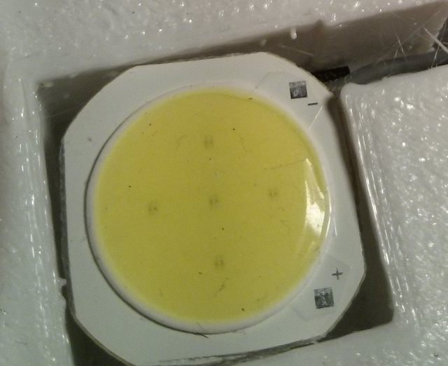
This time around, though, I decided to add a 1 Amp, 1N4002 silicon diode that I had on hand to drop the voltage slightly under 4.5 volts.
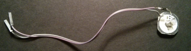
I think my 13-ohm current limiting resistor was probably okay before, and I measured 380 mA when running from the 3 AAA cells on the new flashlight at 4.5 volts. What I may have overlooked were the thermal dynamics of the LEDs. While the LED board may be able to tolerate 5 or 5.1 volts, higher voltages at the same current draw more power, more power creates heat, and more heat then causes them to draw more current, causing a type of thermal runaway effect, and the hotter LEDs draw more current than the cooler ones.
So hopefully I can tamp this down this time around to prevent runaway and prevent the eventual cascade failure that would follow due to the parallel arrangement of the LEDs. I also added some important pullups to the LED. (I'll add the new COB board, diode, and pullups to my next version of the TRILLSAT-1 schematic.)
There is a fallback mechanism where the Pi and ESP actively keep the light off, but if they go down, the ATtinys have control over the light via the MOSI programming line. Unfortunately this line is also used by one Hall-effect sensor, so if the Hall-effect sensor is triggered (sinking), the line cannot be used for other purposes.
This light was invaluable to troubleshooting, as it allowed me to visualize PWM clock pulses when programming before I actually ran the code on the motors. At night, it can also be used for Morse Code signaling and illuminate the ground for the optional camera.
Phasing
If the Hall-effect sensor is not sinking, the LED can also be phased (glowing/pulsing) by using the 8-bit hardware timer, via interrupts, since the 16 bit timer and the 8-bit clock lines are already in use. This creates a nice effect inside the dark Ark interior when the door is opened in Demo Mode. I like to build "mysterious boxes" and had done something very similar in an old treasure hunt game.
Piezo Speaker
A small non-driven piezo element was installed inside the Radio Box, connected to the Pi GPIO for simple PWM beeps and sounds and can be used as a free-fall warning if the accelerometer's free-fall detection is enabled.
Optional Camera
The Pi Zero camera was too expensive for me to add, so I just left a spot for it. The camera does not consume a USB port, and the panel tilt can provide different viewing angles. A mirror on the Planetary Mass could be positioned so that it could view different angles. At night, the spotlight can be turned on to illuminate the ground for the camera.
The Pi Zero W's WiFi card can be enabled temporarily to send imagery back to a conventional base computer, as the bandwidth over the ESP8266 is fairly low.
Tethered Haptics Using Morse Pulses
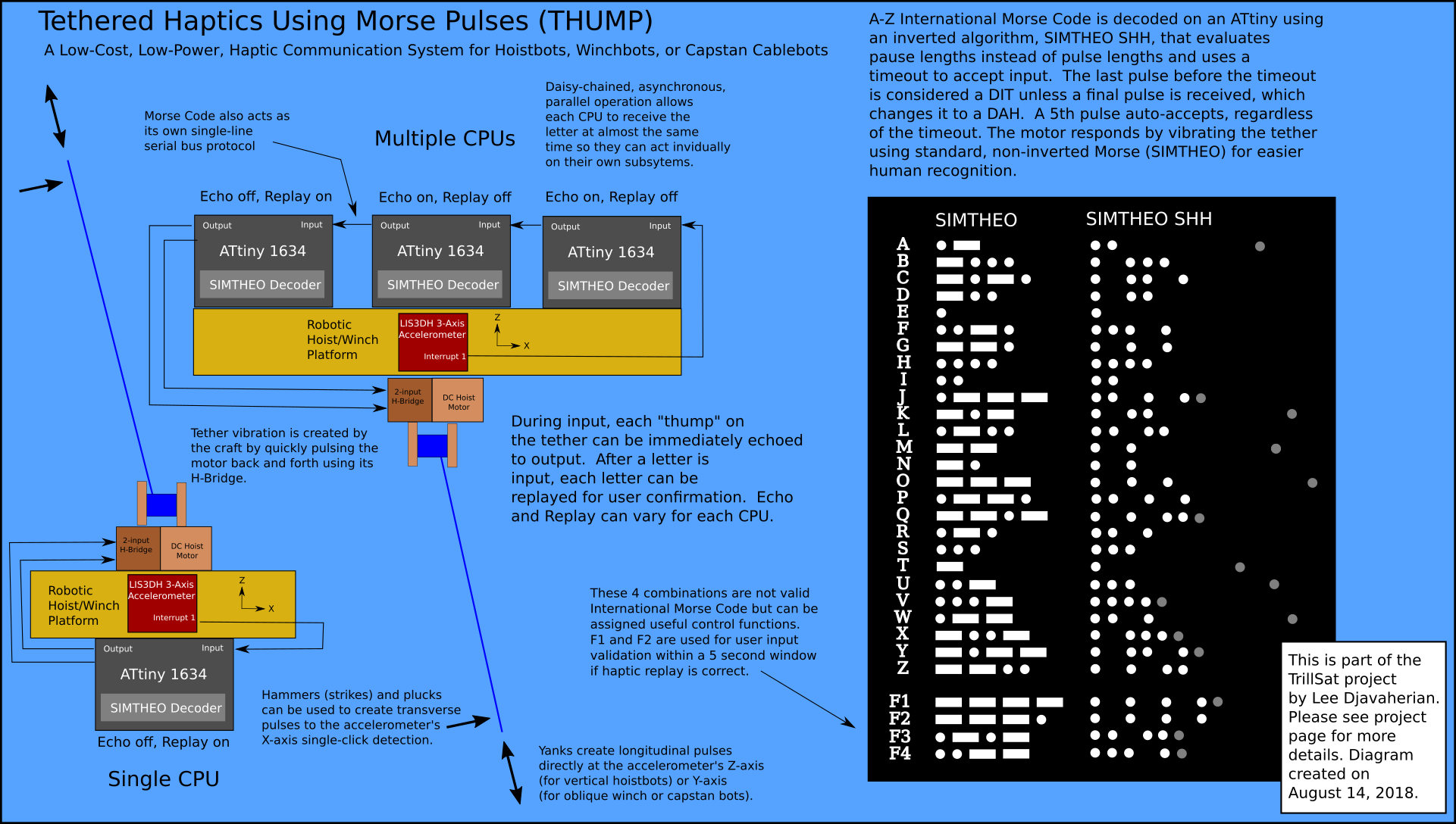
(Click diagram to enlarge)
I realized that Huckleberry, the Power Regulation ATtiny, could potentially detect Morse Code through the accelerometer interrupt via taps and haptic pulses, so I decided to create an experimental system called "Tethered Haptics Using Morse Pulses" to thump on the the tether itself to use it a communication medium, and it can be used with either TrillSat, an oblique capstan-driven cablebot, or a typical hoistbot or winchbot.
Side note added: Please note that this has no relation to a certain political figure in my country, and no relation to the Disney rabbit↗ either. See this section for more details on the various T acronyms.
The craft is anchored on both ends and sails, on what I like to call, a "tether sea". When using the tether for capstan locomotion, the craft acts like a buoyant ship or airship on a medium, but when the tether is used for Morse code communication, it is easy to see that the tether really is a distinct medium. Think of the armed forces of different countries, for instance. They are usually divided into mediums or their absence/combinations (land, air, water, and maybe even space). And even in space, both end-over-end rotation and "gravity-gradient stabilization" can keep a tether taut, and because the tether is the medium, a gas is not needed for wave propagation.
If the XMPP server, ssh/wifi, and the packet radio system all go down and are unavailable, TRILLSAT-1 will still maintain core operation using Sawyer and Huckleberry, but there is no way of communicating with the craft at that point.
Those tiny low-level CPUs, however, can then receive Morse over the tether, and then one of them vibrates the tether to send a haptic response that can be "felt", like an automated version of centuries-old handshaking techniques used in diving by line "tenders", or even a helicopter flight mechanic putting a glove on a rescue cable, when visibility is too low to see any signals.
It might not be widely known that in the middle of the United States where I live, we do have a US Coast Guard presence, the Upper Mississippi River Sector, and years ago, I watched them do rescue demonstrations on the Mississippi using a rescue hoist. Flying machines are fascinating, but flying machines with hoists and tethers even more so. I've also studied that scene in the film The Matrix countless times where Trinity pilots the helicopter with Neo to use the tether to rescue Morpheus, and then Neo uses the tether to rescue Trinity from the copter. It's an inversion on many levels, even ending with the tether changing its anchor points.
I use a subset of International Morse Code for the full A-Z alphabet, but instead of only hoisting something up or down, like in diving or helicopters, the craft is inverted and anchored, and the hoist platform itself is instructed to move up or down. The haptic system requires only the accelerometer interrupt for sensing and uses TrillSat's capstan motor for haptic pulse generation. The operator simply "thumps" the tether (hammering, plucking, or yanking) to instruct the robotic craft to perform any desired function, and the machine vibrates back a response.
If the smartphone runs out of battery power, it needs to dock with TrillSat to recharge, which is hanging high in the air. But how can you issue an XMPP command to lower the craft if the smartphone, the primary client interface, is dead? (a chicken and egg problem). Instead of dismantling the tether completely, the haptic system can allow one to issue commands to lower the craft and turn on the Qi charger so the smartphone can be charged.
If the higher radio CPUs go down the two ATtiny 1634s still maintain craft operation but they cannot connect to the smartphone. But the haptic system speaks directly to the power regulation ATtiny via a single interrupt line and commands can then be issued instructing it to activate the higher systems. It also allows me to quickly shut down all power in an emergency if I cannot access the XMPP server for some reason, which happened in March 2018 when my BLDC motor stalled and burned up due to a freak cascade failure. I couldn't open the case fast enough to shut it down. Only one CPU (Huckleberry, the power control CPU) would need to be working to allow all power to be shutdown using the haptic system.
At night, a flashlight could hypothetically be used to enter Morse Code into the CdS LDRs to enter commands if the radios are offline (or the clients are unavailable) but the ATtinys are still operational. The East-facing photocell, which is tilted towards the ground during sunrise could sense human-sent Morse code at a low baudrate and the LED spotlight could be flashed in response. A passcode could be set in advance over the encrypted WiFi and later reset over WiFi to prevent a replay attack from someone that may have visually recorded the light flashes. But this would only work at night since in the day, when solar power is at its maximum, the photocells are blinded to any flashlight signals.
The haptic system works day or night, doesn't require a flashlight. As long as a person can crawl and feel their way to the tether anchored to the ground, then they could potentially send rudimentary SIMTHEO SHH commands to the unit. On TrillSat, the haptic system cannot directly send communication over the radio, since the radio is controlled by the Raspberry Pi Zero W, but the ESP8266 could be configured on boot to use I2C to check for an emergency message on either of the ATtinys, and then boot up the Raspberry Pi Zero W, which then reads that message and sends it over packet radio (of course, this would need another layer of input validation/error checking).
It's great in testing, too. If it is resting on a table, I can easily just tap the case to issue commands which I otherwise couldn't issue over XMPP (such as turning on the ESP8266 and XMPP server itself, switching to wifi client mode, etc).
The Mysterious Wave Pulse
When you pluck a string at one fixed end it induces a wave pulse that travels to the other end, where it encounters the craft's accelerometer. That's really all I care about.
But the wave pulse has other plans in mind...
It can reflect, even going 180 degrees out of phase, and some of the energy will increase the momentum of the craft but decrease the momentum of the pulse (conservation of momentum). And if you don't pluck the string at the very end, you'll create two transverse wave pulses in opposite directions--one will hit the fixed end and reflect 180 degrees out of phase, and TWO pulses will reach the craft, the intended one, and shortly thereafter, its inverted twin. Luckily, the accelerometer can be told to ignore pulses in the wrong direction (which I didn't need to utilize) and ignore pulses that are too close. It's only the first pulse that reaches the craft that I need to detect.
A traditional hoistbot acts like the free end of a string with a heavy mass, and even acts like a mass on a spring, and TrillSat acts more like a fixed end and reflects some of the energy back 180 degrees out of phase. If the pulse length was very large, TrillSat would probably let the pulse pass underneath, like a ship in the ocean, but the short pulses used in the haptic system are like small waves crashing into the hull.
I don't need to worry too much about what happens after that first pulse reaches the craft, as long the others invert or damp away quickly. There is the possibility of constructive "interference" when two waves happen to collide to equal the sum of their amplitudes. I just need it to be within the threshold and timing windows of the accelerometer. The accelerometer will see a spike in acceleration as the pulse passes, and hopefully, if I configured it correctly, ignore subsequent pulses until the next real pulse. Interestingly, people have also used MEMS accelerometers as pickups for musical instruments, a function not unlike what I am trying to do. And we know that tethers can send a lot of information in their vibration, as tin cans and string can even create a telephone↗ using longitudinal waves.
But music is far more complex, and weird phenomena start to occur (resonance, standing waves, harmonics, etc). I shouldn't have to worry about that with widely spaced pulses. Some physical phenomena such as wind, hail, etc., could vibrate the string in unforeseen ways, but there are simple, discrete ways of stochastic error-checking if noise is a problem.
For the haptic system there were 6 main factors that concerned me: the type of tether (nylon paracord for example), the type of thump used (a hammer, pluck, or yank), the length of the tether, the weight of the craft, the accelerometer settings, and the tilt of the panel (since gravity affected the sensitivity of the accelerometer along that axis).
There are all kinds of dynamics that can be calculated that don't really affect detection ability, but are interesting, nonetheless. For example, the weight increases the tension, and greater tension increases the pulse speed. The type of tether determines its density, and greater density lowers the pulse speed. The speed of the pulse divided by twice the tether length determines its frequency. So, like a guitar string, when you stretch the tether, it increases tension and also becomes less linearly dense, both of which increase pulse speed, which increase frequency.
Have you ever wondered why lower-pitch guitar strings are so thick? Not being a musician, I had always thought it was because they have to be stronger, but, wait--then I started thinking about this further--they don't have to be tuned as tight as the higher pitched strings (because at least I know, with my limited knowledge, that the tighter the string, the higher the pitch). So what is going on? Well, remember that linear density? More mass seems to be added to them on purpose, just coiled around a core, to increase their "mass per unit length" (linear density) which lowers pulse speed, which lowers frequency. Sneaky, sneaky.
I had always assumed that since the strings were all the same length on the neck that tension was solely how they were tuned, but mass is another variable. Note that my father's santur, a type of dulcimer, uses bridges spaced at different lengths (in a trapezoid) and is percussively hammered instead of strummed or plucked.
While accelerometers can detect wave pulses, and can even act as pickups for musical instruments, the problem with using them for single-pulse Morse code detection is the acceleration itself: Morse encodes information in the pulse length (a DIT being 1 unit and a DAH being 3 units, the units are relative). Creating an acceleration pulse is relatively easy--you just thump the tether sufficiently to exceed thresholds within certain timing intervals, all of which can be configured with the built-in single-click interrupt mode that I used on an LIS3DH accelerometer. But creating a pulse 3 times longer to signify a DAH would require massive thrashing of the tether, a continuous acceleration, like a rocket, which is not practical. A hammer, pluck, or yank isn't going to create a continuous acceleration.
A DAH could also conceivably be sent in the amplitude, by plucking or hammering the tether 3 times harder to create a larger spike, instead of a longer one, but the accelerometer interrupt is binary. You wouldn't be able to determine if a DIT or DAH triggered the interrupt. But, interestingly, the LIS3DH has 2 interrupts. However, only one of them is exposed in the Adafruit board that I use (which has other nice features like a controllable LDO regulator). Even if I was able to use that second interrupt, this would force the user's timing to be very strict and would not allow my algorithm to adapt to the user's speed. The I2C bus could be used if the pulse speed was within its configured bandwidth, but the ATtiny 1634s are slave-only I2C devices, and even if a software master was written for them, this adds a lot of additional complexity to the system that simply doesn't need to be there. And what if it was already hard to generate that first pulse, let alone one 3 times larger?
For example, if a hoist robot is really, really heavy, hammers (perhaps even using an actual hammer) may be the only simple option left to generate a sufficient amplitude due to the high string tension. Think about the tension in a hammered instrument like a piano, for example, which is massive, versus that of a plucked or bowed instrument, like a harp or violin, which is less. A harpsichord, for example, has much less tension than a piano.
Another option is to use a "bowing" effect, similar to a violin, creating a back-and-forth acceleration, like a series of plucks, long enough to be recognized as a DAH (and have the accelerometer check for a quick succession of spikes), but this would require a bow, perhaps a jagged piece of plastic, to rub against the paracord, but such a device may not be available. Also, this would introduce those complex wave interactions that I want to avoid. But it's not out of the question--it might actually be a very useful tool in the future. But for now, I'm just using human hands to interact with the tether.
Yanking is a different way of generating the waves. It is percussive, like Fred Astaire tapping a cane on the ground, and creates longitudinal waves in the tether along the Z-axis. A yank is simple for a human to perform, and it can generate clean pulses in certain situations. If the weight is light enough, a person could just pull the craft towards them slowly and then release the tether and let it fall back, like a dog running until it hit the end of its leash--the moving accelerometer would register a sharp acceleration when brought to an abrupt halt (as long as the winch held fast). This would induce an acceleration spike directly at the craft itself, and all other pulses could be ignored during a short window. But if the craft is heavy or both ends are anchored, it takes more force to induce a pulse.
Now let's think of the second part of the haptic system, haptic motor feedback. For a simple hoistbot, it's easy, simply drive the hoist or winch motor back and forth in rapid succession, using an H-Bridge for polarity reversal, and it will create that percussive yank effect which can be felt by a person with their hand on the tether. Because the robot is much faster than a human, it can create a constant vibration (like the bowing effect mentioned earlier) and we don't need to worry about machine recognition now--a human is recognizing it. But TrillSat is a catenary capstan craft anchored at two places (in my case a tree and the ground) and when the craft is up high, the tree begins to take more of the weight, and that end is where those pulses will be felt the most. But I'm on the ground section, so the pulses are more muted. However, in addition to the capstan for locomotion, I use an eccentric mass for solar panel tilt control, and this mass can be vibrated back-and-forth to generate a similar effect, even changing the axis on which it vibrates based on its cardinal orientation. Perfect. In other words, TrillSat doesn't have to just send a "yank", it can also send a hammer/pluck kind of vibration.
Creating a Haptic Morse Decoder
So for Morse code detection, I had to create an inverted Morse code algorithm, called SIMTHEO SHH (as in "shh, quiet!") which times the silent pause lengths between the pulses and not the pulse lengths. But for Morse code generation, I simply used normal, non-inverted Morse code to ease human recognition. In 2016 researchers have shown that haptic vibrations speed up the learning of Morse code, so the haptic output vibration provides an excellent teaching tool.
When you use the pauses to differentiate, the computer can't tell whether or not the last element is a DIT or DAH, since it doesn't know when your last pause ended. It has to wait for a long pause before timing out and accepting the input and cannot rely on a final thump, for example.
So SIMTHEO SHH assumes that your last element is a DIT. But if your last element is a DAH, you simply wait a long pause (but not too long, about 4 DAHs) and send a final thump, and it changes it to a DAH. If you don't wait long enough, it will think that last thump is an element, and if you wait too long, it will timeout, but there is this zone of "just long enough". It uses timeouts to accept user input, but if you enter that just-long-enough last pulse, it assumes you are done and considers it an input.
EEPROM Passcode Lock
A rudimentary two-capital-letter passcode lock system was added to the haptic system which allows 676 combinations, mainly to prevent weather or animals from unlocking the haptic system and spontaneously entering commands. The code is set via XMPP beforehand and stored on the EEPROMs of both ATtiny microcontrollers so that the lock remains in effect even after a total power outage.
The craft will replay the letter it received back to the user by vibrating the tether, and if correct, the user enters a validation code within a 5-second window to confirm. This validation code is what I call F1 or F2, two of the 4 four-element sequences that aren't valid International Morse Code at all. The way it works is that you send a letter, the robot vibrates the tether to the user, and if correct, within 5 seconds you begin to send one of those validation codes (just like you would a normal letter). If the code is correct, the CPU (or all of the CPUs in in parallel) consider it a command and process whatever they are programmed to do. The reason I used both F1 and F2 is due to their ease of entering using SIMTHEO SHH, their similarity, and the potential to allow the one I choose to also convey an additional binary meaning, perhaps signifying ON/OFF or UP/DOWN, for example, as in "Yes, I do confirm that M to turn on the motor is correct, and by the way, its direction is DOWN."
Daisy-Chained, Parallel Operation Using Morse as a Bus Protocol
I maxed out the I/O pins on both microcontrollers, even overloading the SPI MISO (Master Input Slave Output) line with multiple functions (occasional in-circuit programming, LED spotlight, hall-effect sensor, voltage-divider for level shifting). Both microcontrollers share this line for programming, and the Pi just controls their individual reset lines to select which one actually receives the code, so this was an ideal pin to use to allow communication between the two ATtinys.
So I designed the SIMTHEO Decoder to allow operation in parallel over a single line with the option of running a separate instance running asynchronously on each chip.
I configured the ATtiny that reads the LIS3DH interrupt to use that line to send output, and the ATtiny that controls the motor uses it to receive input. Two variables were created, morse_echo and morse_replay which can be toggled to create a daisy-chain system, where one CPU receives the signal, echoes the signal to the other CPU (and then both CPUs decode the signal almost simultaneously). Several CPUs could be chained together in this way without adversely affecting timing. The first CPUs in the chain simply have morse_echo enabled and morse_replay disabled, and the final one controls the motor and is set to morse_echo disabled and morse_replay enabled.
These two options also allow different variations. For example, I can turn off all other CPUs and leave only the first one enabled with echo and replay. In my case, its output also controls an LED spotlight, so it serves as a quiet, visual way to test the system. Because they are variables, I can change them on-the-fly during testing, and so I added an XMPP command called "pulsemode" to switch between the haptic and LED modes when the ESP8266 and Raspberry Pi Zero W were still online.
The chips all interpret the Morse code signal at the same time and interpret the command in their own unique way. If both chips receive "L" to lower the craft, for example, Huckleberry might turn on the power and Sawyer might delay a second and turn on the motor and read the hall-effect sensors until the craft is lowered. Neither CPU really knows what the other is doing, but together they achieve something greater than the sum of their parts. No special protocols are needed, either. All CPUs simply use Morse. It becomes its own single-line serial bus protocol by default.
I keep Huckleberry and Sawyer powered up at all times, but one can also enable the ATtiny sleep mode and the Morse pulses will activate the interrupts and wake the CPU, then put it back to sleep when done, something I did with my Morse code roguelike game to save power (allowing it to run off of a CR2032 button cell battery for years, for example). Roguelike games are turn-based, so this worked very well. The LIS3DH can also be put to sleep and set to "inertial wake", but in my prototype, I leave it running the whole time, and it uses very little power.
The LIS3DH runs at 3.3v logic, but I run the two ATtiny 1634s on TrillSat at 5 volt logic. As long as I don't turn on the pullup resistor on the ATtiny (or set it to an output high) I can safely read the interrupt from the LIS3DH which swings a full logic 0 to 1, and a 3.3v high is still within the range of a logic level 5 volt high.
I used the single-click interrupt mode of the LIS3DH to detect the pulses which can be configured with several parameters. I wasn't sure at first how well thumps on the paracord would be detected by a mode configured for "click" detection, but it works surprisingly well in testing, and I didn't need to worry about that inverted, reflected pulse (or configure a single-direction detection) if I pulse it at the end of the tether. And interestingly, plucking the paracord like a musical instrument (hard enough to create a low-frequency sound) works best for TrillSat--the spike in amplitude is detected, and subsequent vibrations seem to damp quickly beneath the detection threshold. The latency can be configured to set the interrupt pulse length, which is great since it standardizes the signal and makes it easier for my decoding algorithm. I've only tested the haptic system on my wooden Test Frame so far, and I don't know how long the tether has to be before it becomes unreliable, but I would expect that it would work on a much longer tether as long as it is taut, which is pretty much guaranteed in my case since it has to lift an 8.28 lb (3.76 kg) craft. And a longitudinal "yank" would work at extremely long distances if the right type of tether was used. Think of flying a kite--the kite can be hundreds of meters away and one can still yank the string to dramatically affect it. Of course, the catenary adds another variable which creates slack.
I also had to invert the interrupt logic, as I was testing it earlier using a 5v pullup to ground switch (where keying the switch created a logic 0), and this allowed me to quickly swap out my switch and plug in the LIS3DH interrupt line. I used my own external pullup since it was too dangerous to turn on the ATtiny internal pullup or I might forget to turn it off and damage the LIS3DH 3.3v logic.
Once the ATtiny receives the signal, it sends back a haptic response by pulsing the brushed DC drive motor which moves a 458g (around 1 lb) eccentric mass at full current back and forth at 30 ms intervals. Smaller intervals were too faint to be felt, and larger ones cause more thrashing of the tether, but this would vary depending on the type of craft. I had to be careful to also disable the haptic sensing on Huckleberry during the haptic motor replay on Sawyer or else a feedback loop would occur when using parallel CPUs (which was interesting to witness, as it seems to slowly decay to an equilibrium point). Therefore, when replay_mode is set to 0 and echo_mode is set to 1, it knows that it is not the final haptic motor and creates a short delay.
As mentioned earlier, I also used an interrupt on the ATtiny itself to detect the interrupt generated by the LIS3DH, since my ATtinys do so many things that they have to be fast enough to keep up with the pulses. Once inside the interrupt, I turn interrupts back on to allow my Raspberry Pi I2C processing to work (as it doesn't like delays due to a clock-stretching bug), but I turn the pin that connects to the LIS3DH off, since I don't want it to call itself.
It might also be worth noting that there are several defines in the SIMTHEO.h source code that set the duration for various timing factors (the default duration of a DIT and DAH, for example). These can be tweaked somewhat for the particular situation, but setting them too high could cause integer overflows.
Optional Snail Cam or Escapement Anchor
Because TrillSat is designed to be anchored to the ground, the anchor itself can include a small, weatherproof tool to hammer/pluck the line. This might make it easier for me to quickly generate clean pulses (or even generate a bowing effect).
For example, a simple "snail cam", a cam shaped like a snail shell, with a tiny crank could rotated to force down the tether until the cam reaches the drop point, at which time the tether quickly snaps back, generating that acceleration pulse. The cam can be attached directly to the anchor, and a frame could be tied to the end of the tether which fits around the cam. Then all the person would have to do is turn a lever or knob to generate a series of pulses. This would be easy to 3D print, weatherproof, and have few moving parts.
Or a simple set of notches could be attached to the end of the tether, and a rotating gear could pull the tether until it slips off the notch, at which point the tether springs back, similar in some ways to a mechanical escapement.
Emergency Landing
One of the benefits of the accelerometer is that it can easily detect high winds and under extremely windy conditions, the unit can also be programmed to "land" itself, driving down into the ground, parking the Planetary Mass.
Detecting impact with the ground could also be done with the accelerometer. The Hall-effect sensors could also detect a stall condition, implying that the Planetary Mass has impacted. Wind speed generally decreases as you get closer to the ground, so the unit doesn't have to completely land, but just get very low and "anchor" the mass, like a ship at sea to provide some stabilization, fall protection, and distance it from falling tree branches.
Modes
Standard TSO/ITSO Orientation
To avoid confusion, I have defined a standard orientation for the craft with the CPU/radio box being on the LEFT, the power regulation box being on the RIGHT, with the Planetary Mass at Solar Noon at the Radio Box, which is how I originally constructed it. In Test Mode or Demo Mode, the craft is upside-down, called Inverted Trillsat Standard Orientation (ITSO), but in actual use, the left side is also the high side, the right being the lower side and the power regulation box. So when in actual use where the planetary assembly hangs down under gravity, it is in TSO (Trillsat Standard Orientation).
The tether windings also have only one arrangement due to the Pulley Frame orientation, which is based on the Endcap orientation to match the hole up with the external temperature probe. As the tether passes through the pulley frame, it enters at an angle to match up with a particular side of the Capstan at a particular height. No other winding will work correctly, and 5 turns around the capstan seems to be optimal. This allows me to define "UP" and "DOWN" drive motor directions in my code, since only one motor direction will propel the craft in that direction. It also makes sure that the direction of the capstan is properly aligned with the direction of the craft so that the planetary mass can swing properly from West to East during the day to track the sun, which I described in the orbital mechanics section above.
In TSO and ITSO, the USB power terminals are always on the right-hand side. In TSO, GND is closest to the user, 5v is farthest away, and the temperature probe is closest to the user. On the left-hand side, 7.4v is the closest to the user, and the 1-wire terminal is the farthest away, and the temperature probe is away from the user. In ITSO, when the craft is inverted, the closest/farthest arrangement is swapped.
Test Mode
When flipped upside down, the unit's accelerometer can auto-detect orientation and enter "test mode", disabling autonomous systems and displaying statistics on the radio display. It can also use the haptic system to detect taps on the case, which can be very useful to turn power and radio systems on and off during testing when the XMPP server, Pi wifi, and power is unavailable.
Demo Mode
If flipped upside down and installed in the Ark, a command could be issued to enter "demo mode", instructing Sawyer to monitor the CdS LDR that faces the door for abrupt changes in light intensity, signaling that the Ark door has been opened. When the door is opened, it can then phase the LED light to illuminate the craft inside the Ark (or even play a sound on the piezo element). When the door is closed, it can resume its door monitoring until demo mode is canceled.
The Software
Algorithms
I mentioned equations, but often neglected are the algorithms, which aren't as easy to recognize and tend to be more time consuming, as they are often imaginative creations that are customized to the environment. This is the "inner" world, a fractal maze, where Art meets Science. Scientific equations bound many of our concepts, but leave the possibilities within them undefined.
While the core programming was completed in about a year, it will take another year to perfect the algorithms--there is so much more that can be done. I neglected thinking about many of them until the end of the core mechanics, electronics, and programming, since I knew that needed to have everything working in front of me before I could then identify where and how add the higher-level operation; I just had fuzzy initial ideas on what I would try to do. It caused me to realize, however, that algorithms, while high level, have much more in common with "construction", something we often stereotype as a "lesser" skill/craft and not a full-fledged design art.
But algorithms aren't just software constructs. Many are shaped by mechanical constraints, a Path through a Forest, so to speak. Even the way we choose to interact with the craft is an algorithm. If you dropped a ball in a pachinko machine, for example, the ball will follow its own algorithm, there is no "software" there. When you see software as "hardware" and vice-versa, it frees up your ability to design without false constraints (and is something I like to study in my philosophical essays).
In the mechanical world, one may do something like this:
- Imagine
- Design
- Engineer
- Construct
Abstract to tangible, seems straightforward. But in the software world, one may do something like this:
- Imagine
- Design
- Create the program framework/API
- Add the final algorithms
Abstract to tangible? Is there really a difference? It's not as clear.
Before this project, I never thought of algorithms as a last phase of construction, as I even did my radio/PBBS programming before the robotic construction. But when a person assembles a set of measurements and materials in the real world, there are real-world constraints that come into play that change your actions and shape your work, regardless of what the designer/engineer originally imagined or expected. Similarly, those constraints shape your algorithms and the software is not fully "constructed" until they are in place.
Fascinating.
But before I could get to this point, I had to do a lots of things first.
Five Programming Languages
- Bash on the Raspberry Pi Zero W to take advantage of the Arch Linux Unix modularity
- Python 2/3 on the Raspberry Pi Zero W for the bot and PBBS code
- Lua on the ESP8266 (via NodeMCU)
- C (via AVR-GCC and AVR Libc) for the two ATtiny 1634 microcontrollers
- OpenSCAD to parametrically design all parts for 3D printing
Ten Protocols
UART
All four CPUs have at least one hardware UART. This was the primary method of communication between the Pi and UV-5RA, but it wasn't necessary for me to use it on the ATtinys.
I created routines on the Pi and ESP to send/receive messages to/from each other over their hardware UARTs. I also implemented an additional software UART on the Pi using Pigpio to communicate with the UV-5RA.
Creating a Virtual Serial Port
One of the problems I had to overcome was the lack of a second serial port on the Pi Zero W. I did disable Bluetooth to enable the PL011 UART instead of the mini UART, but there doesn't seem to be a way to expose both UARTs at the same time on the GPIO. The ESP8266 was using its only available serial port, uart0, and uart1 is not accessible on the board. But I needed another UART in order to program the UV-5RA radio at the same time.
I used a Python module called "pigpio" which handles this wonderfully and bitbangs a serial port. It also has many other neat functions that were beneficial to this project, with the only downside being that it requires a daemon called pigpiod to run as root, which adds about 10% to the Pi Zero CPU (but that cumbersome daemon turned out to be very useful for something else, as I will discuss later). And it doesn't seem to have the ability to timeout when using the serial port. The Chirp software, for example, relies on the pyserial module for its access to the hardware serial UART, and pyserial includes a timeout parameter, so Chirp is able to handle these types of errors, but this was not possible with pigpio.
While you can set a watchdog timeout in pigpio for the GPIO, for some reason this functionality wasn't added to the bb_serial_read function, from what I can tell. You have to use a combination of its bit bang read function (to read) along with its wave function (to write).
TCP/IP
Since the Pi runs a Linux OS with a full TCP/IP stack, I figured that it would beneficial to utilize this even though the system would not be connected to the Internet during use, as there are many client/server programs that can run over this protocol. Ideally, I would turn off the Pi WiFi to save power, and then pass the traffic through the ESP's WiFi connection. However, this puts a fairly large burden on the ESP's CPU, as this chip was designed to provide a simple WiFi connection and TCP/IP stack to tiny microcontrollers (at slow datarates), not pass high-speed traffic from a large, multitasking OS.
Difficulties of TCP to UART Bridge
Before I decided to create my own XMPP server on the ESP8266, I created a TCP to UART bridge on the ESP using NodeMCU, and this, in conjunction with socat on the Pi Zero, allowed me to connect to the Prosody XMPP server on the Pi Zero at 9600 baud. Socat had to be finessed, however, and it was a little unstable.
Creating a TCP to UART bridge is fairly difficult to do. You can't just jam TCP and serial ports together, as they are fundamentally different protocols. Thorsten von Eicken's article on the Serial bridge↗ does a good job of explaining this. He said:
"The difficulty with network communication and bidirectional TCP communication is that multiple tasks need to be handled in parallel. For example, packets with data may arrive at any time on the TCP connection and need to be received and pushed into the UART. While this is happening, additional packets with more data may arrive and need to be queued. In addition, data can start coming in on the UART at the same time. It needs to be collected, and sent over the TCP connection. Furthermore, additional TCP connections can be established at the same time and add more concurrent activity to the mix."
I read that he struggled with creating a bridge in Lua before eventually creating the popular "esp-link", a bridge in C language, which can run at faster speeds. I tried esp-link, but it did not have the features that I needed (primarily the ability for me to intercept the packets and add my own Lua code).
So I just jammed TCP and the UART together, and it works well enough at 9600 baud for short text strings, but I seem to have corruption issues with a lot of text or higher speeds.
I had to use a while loop to keep socat running on the server, since socat forking didn't work right.
802.11n
This is simply the WiFi-protocol employed by the ESP8266 and Pi Zero W, and I don't have to worry about the protocol itself. However, it is advantageous to use DTIM (mentioned later) to reduce WiFi power usage. I also have programmatic control to power up/down the WiFi module, change the passwords, convert from AP to client modes, etc.
XMPP instead of MQTT
Since I moved the XMPP server into the ESP itself, rather than use Prosody on the Pi Zero, I have avoided the TCP to UART bridge problems and can use this protocol rather reliably for sending short text strings to the ESP or through the ESP to the Pi.
There were no known Lua-based XMPP servers for the ESP8266 at the time I started this project in 2016. It seemed that people are focusing on MQTT instead, a similar messaging protocol that was designed for things like sensor networks, and machine-to-machine communication, not human-to-human communication like XMPP. But many people have adapted MQTT for human communication. NodeMCU does include support for MQTT, and I looked into this as a viable option, but at the time I started the project, I could find no open source Android MQTT clients, and there are few Android clients period. Also, they seemed more designed for communicating with sensors and devices than communicating with another human or even a "bot".
So I asked myself, "What is wrong with XMPP?". It is also a simple protocol, but its popularity has waned in recent years as corporations have created proprietary substitutes. Many cite the problem that XMPP does not work well over non-reliable networks, like mobile networks, as it was designed before their proliferation, but extensions to the protocol have been added and this can be compensated for. I use XMPP on mobile daily with few issues.
So I decided to build a rudimentary XMPP server on the ESP8266 using NodeMCU. It doesn't support the entire protocol, but just does what it needs to allow the open-source Xabber ("version Dev 1.0.74 found on F-Droid) to communicate with it. This allowed me to easily intercept commands meant for the ESP, or forward commands meant for the Pi Zero.
Programming an XMPP Server on the ESP8266
After building a UART to TCP bridge, as mentioned above, socat (using the -v option) revealed to me the simplicity of the communication that was occurring between Xabber (on an Android smartphone) and Prosody (on the Pi Zero), which is one reason it worked very well over 9600 baud. So I started researching the XMPP protocol, and while the specifications are wordy, the actual protocol is very simple, consisting of short text stanzas. After programming the bridge, I was getting more familiar with Lua, which gave me confidence that I could write a simple XMPP server in Lua, just simple enough to convince Xabber that it was a full-blown XMPP server, not to make it fully compliant with the XMPP specs (which is a lot of work and would consume a lot of the precious flash on the ESP8266). I actually ran out of flash memory while programming the ESP and had to use a custom builder to create a version with less modules, to free up some space.
An XMPP session goes something like this:
- Establish opening streams and select encryption mechanism
- Complete password authentication
- Open normal streams
- Bind to resource
- Send initial presence
After that, it is just a matter of responding to queries from the client (Xabber, in this case), such as supplying a roster, sending and receiving messages, sending and updating presence (show and status), returning XMPP pings, and disconnecting.
Parsing XML is fairly difficult if you don't have access to a module to do this for you, but I was familiar with crudely parsing HTML using Perl regex (which many people say not to do) when I programmed a static site generator years earlier. It was "good enough" for my context, and I applied that same pragmatism to this project. However, regex does not exist in Lua's string libraries.
"Unlike several other scripting languages, Lua does not use POSIX regular expressions (regexp) for pattern matching. The main reason for this is size: A typical implementation of POSIX regexp takes more than 4,000 lines of code. This is bigger than all Lua standard libraries together."
--excerpt from Programming in Lua (first edition) by Roberto Ierusalimschy
Lua is a neat, tiny, fast language, but it had to make some compromises, so it has its own style of string functions that aren't like Perl or Python but somewhere in-between, with some omissions, and I had to think about how to best apply them. So by studying the communication between Xabber and Prosody, I just looked for unique text patterns and injected text where necessary to construct the XML elements. My code is crude, but I also didn't want to spend time writing up a proper parser, which might use more flash space. But... it is fast. Prosody itself, was written in Lua, and uses the LuaExpat module for its XML parsing, but this module does not exist in NodeMCU.
One problem that surprised me was the datagram-oriented nature of IP, that the order is not guaranteed to be in sequence, and when I sent some XMPP stanzas over the WiFi to Xabber, Xabber sometimes received them out-of-order, which caused problems.
My server only supports SASL PLAIN encryption, which is not encrypted, but is base64 encoded, with some \0 null characters, as name+password. There is a crypto module in NodeMCU that might be able to handle some of the encrypted states, but again, this would be more difficult to code and consume more space and bandwidth. In fact, I removed both the encoder and crypto modules from my NodeMCU build and did not utilize any base64 decoding functions, deferring to the Bash base64 program to precompute the password string, which I stored literally in the code for validation.
Xabber sends out an XMPP ping every few minutes, and if the server does not respond to the pings, it will eventually mark the connection as offline, even if you send it other things (like presence messages).
I2C
Early on I realized that, due to the Raspberry Pi's hardware I2C clock-stretching bug that that any commands sent from the Pi to the ATtinys would have to get an immediate response to prevent corruption. Well, performing several ADC reads or ramping up a motor speed takes time, for example, so I had to create a mechanism to allow the Pi to initiate a command, allow the ATtinys to process the command on their own, and then use Python to poll the ATtinys for the result before returning the information. This minimized the delays on the I2C line that could encounter the hardware bug. There are software I2C options available for the Raspberry Pi, but they took over the relevant GPIO pins completely and I couldn't dual-use those pin for SPI programming. The 1634 has true hardware I2C, but it is slave only, unlike the newer 1616 which was released while I was working on this project, and it sets a hardware interrupt when in use, jumping to an Interrupt Service Routine (just a C function).
1-Wire
The 1-wire protocol is used to communicate with the four DS18B20+ temperature sensors, but I had some trouble getting the Pi Zero to read all 4 sensors without corruption through Python, but it worked well through BASH scripting run through cron, but this slows my reads a little. On the ESP8266, NodeMCU has 1-wire support, but it also has specific DS18B20 support, which I plan to add later. The ATtiny 1634 microcontrollers lack hardware support for 1-wire, but I didn't really need them to access the DS18B20+ sensors anyway, so there is no reason to implement it in software.
Revisiting AX.25 Packet and APRS
What I really like about packet and APRS is the simplicity and the non-reliance on the Internet. Today we take for granted SMS texting or even Internet-based e-mail and text, but this requires a cell or Internet infrastructure, which might not be available. Towers can get overloaded with connections, routers or servers can go down, signals can't reach areas limited by geography/distance, power outages can take down Internet clients or access points. But AX.25 packet existed before the WWW, before the smartphone era, and has no such dependencies.
When the WWW formed, some of those early AX.25 programmers started incorporating Internet technologies into packet and APRS, which is exactly what I am NOT interested in, since I don't want any reliance on the Internet. So I went back to the roots of packet and APRS and looked at some of the basic functionality that started it.
One of the most basic and underappreciated features of packet radio, for example, is the simple store-and-forward BBS. You don't always need or want the automatic routing, which adds complexity to the network and software. Routing things "manually" is something well-suited for ham radio, as many hams want to know how and via what path their signal traveled. And when you manually route, you have to be aware of where the nodes are, which keeps you in touch with the "physical layer", the planet itself. The network is openly exposed, and when you can't connect, you know where the problem lies and you can come up with ways of fixing or mitigating the problem, instead of just receiving an error message that you could not connect.
One of the things that made the Internet possible was IP (Internet Protocol) which enabled automatic routing of packets, using a 3rd network layer, but AX.25 only uses 2 layers. People have created a 3rd layer, but it is not part of the specification. You can just send out a packet call to a callsign, and if someone is running such a tiny packet BBS, or PBBS, you can leave them a message. This simple mechanic is extremely powerful and important, like e-mail or text messaging without any Internet or cell service whatsoever.
If you've seen some of the other projects I've worked on, you'll notice that I like to work on systems at a particular level of complexity, complex enough to be useful and practical to a knowledgeable person, but not so much as to obscure the other parts of the system, before the stage where something is "abstracted". I write about a particular "zone" in which I like to learn, and this zone is the highest level of complexity in a subject that is not abstracted. I've found that when you work on systems that form lower abstraction layers for something else, you often don't see them for what they are, but only for what they provide to the higher layer.
So by combining the ESP8266, Pi Zero W, and Baofeng UV-5RA, I've got a fairly inexpensive and low-power, WiFi, 2-meter/70 cm computerized transceiver, something that can be capable of hosting a PBBS. I then add this system to the TROT platform controlled by the two ATtiny microcontrollers to harvest power and raise it to a high elevation.
Unix Programming vs. libax25
In Linux, the kernel has built-in support for AX.25, and it does all of the hard work. You just need to write a program to control and interact with it. Since there were no known Python modules available for AX.25 at the time I started this project, there were only two viable methods for programming an AX.25-based system in Linux:
- Use the C libax25 library
- Exploit Unix Programming Techniques
The Packet and APRS communications that I am working with are slow, 1200 baud text streams. Back in the 1980's you could write a 1200-baud BBS (the phone-line version) in interpreted Commodore 64 BASIC (on a 1 Mhz 8-bit CPU) using a software UART (which actually did). The Pi Zero has a 32-bit CPU with 1000 times the clockspeed and a hardware UART, so there is no good reason not to take advantage of a powerful interpreted language.
The more I studied the old AX.25 Linux commands, the more I realized that those programmers thoughtfully included mechanisms for allowing such control from other Linux scripts, eliminating the need to use the C library at all. There do not seem to be many people that have taken advantage of these mechanisms, but I think like a systems programmer, and so, to me, this shows off the modularity and re-usability of the Unix philosophy.
So I decided to exploit the benefits of this modularity: pipe the text streams through old Linux AX.25 commands (that were written in C) and let them interact with the kernel.
KISS
While AX.25 is the radio packet protocol, there is an intermediary protocol needed called KISS. KISS wraps the input in a KISS frame, based on the HDLC protocol, which is the protocol that old AX.25 TNC devices used, which is still expected by many Linux AX.25 tools. In a way, KISS is analogous to SLIP used in the early Internet when modems over serial lines were used to communicate over a TCP/IP stack, except that in this case, it was designed for packet modems over serial lines to communicate over an AX.25 stack.
Creating a Virtual Test Environment
In order to test the system, which occurs frequently during programming, you can't just put the thing on the air, spewing garbage all over the airwaves. Testing it on the air also requires two radio units, a sending and receiving station. So testing it virtually is ideal.
The first thing I had to do was to create the calling and receiving ports in /etc/ax25/axports.
Next, these ports must somehow be linked together, as if they are in constant communication with each other. Luckily, Linux contains a wonderful tool called socat (for socket concatenation) which can create bidirectional connections between two sockets, TCP/UDP ports, or files (and file-like devices), in any combination.
socat -d -d pty,raw,echo=0 pty,raw,echo=0
Will create two pseudoterminals and link them together, so that the input in one appears on the other, and vice-versa. This formed the basis of an on-the-air link.
The next step is to attach each pseudoterminal to an AX.25 device in KISS mode.
kissattach /dev/pts/[num1] [AX.25 calling port]
kissattach /dev/pts/[num2] [AX.25 receiving port]
Each kissattach line creates a virtual AX.25 port (which can be viewed in ifconfig) which is attached to a Linux device path. It needs to be run for each pseudoterminal.
Once these steps are done, it is just a matter of telling any Linux AX.25 tool which port to use, and it will begin sending or receiving on that port. So, in different terminal windows, you can launch the calling software on the calling port and the receiving software on the receiving port, and they will be able to communicate with each other.
A really neat thing about socat, however, is that it can also intercept packets in transit and display them to another window, using the -v option, allowing you to view the communication in real-time, which was invaluable for debugging my UART to TCP bridge and my XMPP server.
In Linux, the receiving end of an AX.25 connection is handled by ax25d, a daemon that listens for an incoming connection and launches a program to connect to it, connecting up the sockets. However, if your receiving program crashes due to a bug, the socket will remain open and there is no way that I could find to close it. There is a command called axctl which has limited control over an existing AX.25 connection, but it can't kill a connection after a crash. This caused such difficulty that I had to bypass the AX.25 subsystem during most of my testing and had to tell my programs to talk directly to each other.
I did most of my programming over a WiFi SSH connection on the Pi Zero, and I had to keep reminding myself that print statements do not work as expected. Since the ESP's UART is being consumed by the program on the Pi Zero, any print statements in the Lua code are sent over the UART to the program. Sometimes I would connect to the Lua interpreter on the ESP using Minicom to debug it or perform a node.restart() to reset it, but if I forgot to close Minicom or remove any debugging print statements that I added, it would interfere with the commands sent to the Pi Zero.
UV-5R Serial
The UV-5RA, one of the Baofeng UV-5R series of radios, is a clone-mode radio only, and the only way to programmatically control it is to flash its memory, overwriting the previous contents, at which point the radio reboots with the new settings. Luckily the radio keeps its "work mode" settings in this flash memory, which include the current frequency it is using. So it is just a matter of overwriting this frequency with a new one, and then the radio reboot on the new frequency.
Well, previously, the only way to do this was to use the Chirp programming software, excellent software that performs such operations for a variety of different radio models. I built a data interface to enable Chirp to program this radio using a Raspberry Pi 2, while at the same time, allow packet radio and PTT functionality. But, during this project, I couldn't use Chirp since I was running the entire system headless (no external monitor) and thus was not running X-Windows. But Chirp requires a GUI, and there is no good way to control this software programmatically.
In the Chirp repositories, however, there was a program called Chirpc, which does just this--it allows command-line programmatic control of Chirp. However, it also had some limitations, as it cannot read/write the exact memory location needed to change the frequency. In the GUI version of Chirp, this can be done by editing a field, but in Chirpc, there was no way to access this. The only thing you can do is download the entire memory to file, and upload the file back to the radio, both of which take quite a bit of time to complete, as they are touching every memory location.
But what was wonderful about Chirpc is that its source code was fairly clear, and it provided insight onto how the Chirp actually communicates with the radio so that I could determine the radio programming protocol. I assume that the Chirp programmers put a serial sniffer in place to obtain this protocol and then replicated this in their own software to program the radio, but I don't know for sure.
Changing the Frequency of the UV-5RA
The system has the ability to tell the UV-5RA transceiver to change frequencies on-the-fly. It turns out that you don't have to actually clone (read/write) the entire flash, but this can be done in much smaller 16-byte blocks, which is much faster and doesn't add needless writes to the flash.
To figure out where the frequency was stored, I first downloaded the entire flash to a file and then ran "hexdump -C" on the file and redirected this to another file, converting it to text. Then I ran diff between these 2 text files to show me where the change was. I suppose I could have also used hexdiff instead.
On my radio, for example, the 0F10 location (the 3856th byte from the beginning of the file) was where the frequency of the VFO A is stored, in 8 bytes, the decimal position value stored in each byte.
Maxing out the ATtinys
It is easy to forget that multiprocess and multiuser programming are very high-level concepts made possible by modern computers and operating systems, and, in a very fractal way, similar problems and solutions also manifest at low levels.
While the Pi and ESP work together to manage the high-level functions in BASH, Python and Lua, the two ATtiny 1634 8-bit microcontrollers, Sawyer and Huckleberry, perform most of the low-level functions of the craft and were a joy to program at first, allowing me to work in pure C language without worrying about higher-level concepts or constructs. But as I began to load the entire burden upon them, I had to create a few higher level constructs and started to hit the limits of their capabilities.
I used hardware functions such as:
- True Hardware Slave I2C
- In-Circuit SPI Programming
- Both 16-bit and 8-bit hardware timers & PWM
- I2C, Timer, and External Pin Change Interrupts
- 10-bit hardware ADC & Internal Voltage Reference
- All of the available digital I/O pins (even overloading some with multiple circuits)
- Max clock (via internal oscillator only) of 8 Mhz
The ATtiny 1616 was too new at the time so I didn't use it, but it would have had several advantages over the 1634. However, many of the 1634 concepts are still relevant to the 1616.
I decided not to put the chips to sleep to conserve power, as the benefits in this use case didn't outweigh the drawbacks.
Jobs
Even if I could figure out a way to enable proper I2C clock stretching to overcome the Pi hardware bug, the I2C line would still be tied up for long periods, so I decided to might as well go ahead and build a job-processing mechanism and continue to use the buggy hardware I2C. It is fairly simple and relies on the main loop to check global variables and process.
Interrupts
Interrupts are interesting concepts, which I first encountered when I programmed the Commodore 64 as a teenager (remember the old IRQ and NMI?). Before the era of multitasking operating systems, object-oriented and event-driven programming, a lot of programming was imperative, a long sequence of instructions in a main loop, with various levels of modularity. I was a product of the microcomputer revolution and didn't encounter mainframe Unix, or its more advanced concepts, until years later. So we 8-bit programmers often ended up having to build our own mini OSes anytime we needed to accomplish certain abstractions. There weren't even hardware "drivers" in those days, each driver was custom-written by the programmer in his program to talk to specific hardware.
The interrupt was a way to allow the CPUs attention, which was processing the main loop, to be interrupted, prompting it to work on something else for a short time and then resume working on the main loop again. You get a very visceral feel for the sequential nature of the CPU--this thing cannot multitask but just creates the illusion of such due to its sheer speed. The 6510 (based on the 6502) that I used to program was a 1 Mhz CPU, which was unbelievably fast to me as I had to start thinking in microseconds for the first time. The most precise digital watches of the time had stopwatches with hundredths of a second precision... but not thousands (milliseconds), and surely not microseconds, with its strange Greek Mu.
But, when I was young, I learned that this speed is not a fast as we imagine it to be, once you start to divide it up... For example, a relatively modest motor running at 6,000 RPM spends 1/6,000th of a minute on one revolution, which is 1/100th of a second. If you divide that revolution into 360 degrees, there are around 1/36000 seconds or approximately 28 microseconds per degree. So we don't have a lot of time to do anything as that degree elapses, especially when your CPU instructions start to eat into those precious 28 microseconds, not to mention any other interrupts that it needs to process and then return to before that 28 microseconds passes. On the C64, I remember that the BASIC interpreter was too slow, and even using assembly language, I had to be cognizant to keep my code small enough to perform rudimentary signal processing of an American telephone ring which was a mere 20 Hz, or 1/20th of a second, but there were 2 polarity changes per cycle, at 1/40th of a second.
In the following decades, the computing world has tried to tackle this problem in the ways that we always thought it would: either make the computer run faster (Time), or run more computers simultaneously (Space).
The ATtiny 1634s are modern 8-bit computers, engineered for low size, cost, and power, using knowledge that we've learned in the 30+ years since my microcomputing childhood and they indeed run faster, as I run them at 8 Mhz on the internal oscillator, but they also contain hardware timers, separate circuits that essentially run in parallel, asynchronously alongside the CPU. Some people have even used the timer phase difference to generate random numbers, something the CPU itself cannot do.
Timers
I maxed out the 16-bit timer to drive the H-Bridge motor at frequencies high enough to lower voltage ripple yet low enough for the capacitance of my H-Bridge MOSFETs and deadtime delays. I needed the full 16-bit resolution to enable Phase & Frequency Correct mode at these frequencies. The timer automatically sends inverted pulses to the motors at an adequate resolution, toggling the 2 pins, which is great.
But since the 16-bit timer was already used, and there will be times when I have to run both motors at the same time, I maxed out the 8-bit timer to drive the 3-phase BLDC motor (and it also provides a timing source for the software in general). The gyro isn't as critical as the H-Bridge as it has lower current requirements, I used a fairly robust L6234 motor controller IC, and just spins at a constant speed most of the time and doesn't need to be phase accurate (I used Fast PWM mode).
The 8-bit timer, though, could not drive the BLDC motor pins directly, firstly because the pins were already in use with other circuits, and secondly because there are 3 motor phases, not just 2 like on the H-Bridge. Luckily, the ATtiny 1634 allows the timer to generate hardware PWM interrupts without setting an external pin, and then I was able to use these interrupts to activate PWM on the relevant motor phase indirectly, through my own software routines.
None of this was easy, though, primarily because there were also external hardware pin-change interrupts generated by the gyro Hall-effect sensors at very rapid intervals, which are independent of the timers, and the interrupts can interfere with each other if they take up too much time, causing a halting or cascade effect, and it was also difficult because of the limited 8-bit resolution of the timer in-conjunction with a slower clock prescaler setting.
The clock prescalers are interesting as they allow you to slow down the timer to less than the CPU, which can make the timer values more relevant and useful to you within their resolution depending on the application. For the 16-bit timer, I ran it at full speed with no prescaler (8 Mhz) as much of the speed is eaten up by the Phase & Frequency Correct mode at high frequencies, but for the 8-bit timer, I ran it with a divide-by-8 prescaler (1 Mhz) just like the old C64. This allowed me to keep the 8-bit overflow within a reasonable range. I told the overflow and the TOP match of the PWM to both set interrupts (which then gave me the chance to programatically toggle those PWM pin states) and it also allowed me to increment a 32-bit variable called Timer and a 16-bit variable called Big_Timer, large enough to increase the theoretical resolution of the timer to capture several years and prevent any overflow errors.
But the problem with increasing your timer capacity using software routines, rather than allowing the hardware to do it, is that your CPU has to then increment the timer variables, which means that when your CPU is running other routines, it can't simply check those variables for the current time (since it hasn't gotten the chance to increment them yet). In other words, true parallel operation is needed.
There was no simple solution. Even borrowing some spare functions from the 16-bit timer would have the same problem, as running at 8 Mhz, a 16-bit variable would overflow approximately every 15 microseconds. So I had to round the timer values, only using the larger values stored during the overflow, and could not pull live from the hardware 8-bit timer without being certain that the larger variables were accurate.
Three Gyro Modes
This was made even more complicated by the Gyrofan Hall-effect interrupts that were set if any of the 3 BLDC Hall-effect sensor pins changed states, indicating that the motor had entered the next phase. Due to its speed and the fact that my code was rather long and had delays, I figured noise/debouncing/hysteresis was not a problem (like it was when I tried to use comparators for undervoltage cutoff) and it wasn't. I was able to get the PWM pulses within a crude resolution. They had to be extremely fast, which is why I didn't want to increase the 8-bit timer prescaler even more, since there are 36 electrical phases per mechanical revolution, and the PWM must be enacted during this 1/36th revolution, which doesn't give my software routines much time to work with. Running the 8-bit timer with no prescaler wouldn't work very well either since the timer is running as fast as the code that is running within it. The code would slow down the timer...
Even now, without an oscilloscope, I'm not sure if I'm skipping a few steps--the RPM readings are unstable and I can audibly notice irregularities, so this is probably the case, but I won't slow the clock even further or I won't have useful PWM.
When I run at the slowest PWM, the gyro still runs very fast as it simply goes full out until it hits the next Hall-effect sensor, and so on... So, to slow it further, I had to incorporate a type of "lock" drive, similar to the Locked-Antiphase drive I added to the H-Bridge. But with BLDC motors, you don't have to create 2 inverted pulses, you only need to just "hold" one pulse longer than needed, as the rotor will try to hold to that stator coil. So I added a delay routine, but this was complicated when combined with the Hall-effect interrupts.
The external pin change interrupt routine doesn't like to be delayed, it holds up the timer and I2C interrupts. I tried nesting interrupts by adding an sei() command, but it caused weird issues that took me days to solve without success. It reminded me of the worst bugs I experienced with buffering/deadlock problems during the concurrent programming of Python on the Pi Zero. Parallel operations are hard for our mind to visualize (as we consciously focus in a sequential way just like a digital computer). So I compromised and created 3 modes of Gyro operation.
- BLDC_FAST_MODE - For the highest maximum RPM, slightly greater than max PWM: Turn off PWM and turn off ctc interrupt, allow max voltage, allow pin change interrupts to drive the next phase automatically. It could run too fast and cause the gyro to disintegrate.
- BLDC_PWM_mode - For RPMs above 1360 but below 1520: Turn on PWM, allow partial voltage, allow pin change interrupts to drive the next phase automatically. This still runs moderately fast and low power, but gyro is weak at the lowest voltages.
- BLDC_LOCK_MODE - For RPMs below 1000: Continue to use PWM, but also allow the pin change interrupt to indicate the phase to the timer, then rely on the 8-bit timer overflow interrupt to activate the phase.
Once the Gyrofan is moving, global variables control the PWM voltage and the lock delay which can be used by other jobs in the main loop to provide functions such as ramp up/down.
I decided not to use an open-loop PMSM↗ (Permanent Magnet Synchronous Motor) mode and always include the hall feedback.
Lock mode causes a nice holding effect that can slow the Gyrofan to a crawl if needed. At slow speeds, it's not smooth, as its not a true sine wave, but I only run it at slow speeds when ramping up at startup. At slower speeds, the PWM voltage can be increased to prevent slipping, then this voltage can be lowered during the constant run phase. If higher speeds are needed, it could even transition to PWM or FAST mode, theoretically.
Unfortunately, my lock mode can't go much faster than around 1000 RPM due to the lowest minimum delay imposed by the prescaled timer overflow, which is 256 times more coarse than its smallest value. But if you set the RPM to 1360 or above, the system will switch to FAST mode, which can go up to around 1520 rpm. If you set the RPM to 1520 or above, the system will go to its fastest possible speed by disabling PWM altogether and perform full pulse on each step.
I was able to count the phase transitions and compare them to the (crude) elapsed time of this overflow timer to obtain a rough RPM. I couldn't use the more granular hardware register TCNT0 since once I was in my own code in another interrupt, I couldn't be certain exactly when TCNT0 would overflow again, making the number unreliable.
My original idea was to time the very short transitions and then get an RPM, and then boost or lower the PWM voltage dynamically to hold this RPM, but these time frames were too short for such quick response (especially when RPM computations are also needed), so I decided to count 6 mechanical revolutions (216 electrical steps or phases). This means that the gyro cannot react quickly at low RPMs to maintain its speed. If I could increase this measurement speed, like a closed-loop PID algorithm, it could better compensate for any torque changes to the craft due to wind or to counter drive motor torque.
Minimizing Power Usage
Since this system is designed to run without any dependencies on the power grid, its current draw had to be minimized to keep the size, weight, and cost of the batteries and solar panels as small as possible. The ESP8266, Pi Zero, and ATtinys are already some of the lowest-power devices in their classes, and the Baofeng UV-5RA draws fairly low amounts of current in its standby mode.
Minimizing the CPU usage also keeps the current down, and so blocking functions and event-driven routines were used as much as possible. The biggest fraction of CPU is used by Direwolf, as it has to do real-time audio signal processing, and coming in second is the pigpio library's pigpiod daemon, which has to monitor the GPIO lines. But in general, with both of them running, the CPU stays at around 30%.
Applying the ESP's DTIM sleep modes in conjunction with a DTIM router helps, and the ESP can be put into timed deep sleep when needed, with the ability to power down the Pi Zero and radio completely.
An Android smartphone running Xabber is also a required component, and turning of the cell radio and using WiFi DTIM minimizes power. I relied on Xabber's own XMPP pings instead of sending my own, to keep transmissions minimized.
The Delta-v Motor Drive System
When trying to drive the sinusoidal Three-Tridant Orbital Mechanics of the main drive motor, it became apparent in testing that my terrestrial, truck-driver analogy was too simplistic and any heuristics that I created to "drive" the mass over that series of metaphorical, sinusoidal hills were too crude to keep the planetary mass rotating at a constant speed, and I didn't want to employ any significant AI or learning algorithm to improve my driver's ability, so to speak (which would also add large amounts of stress to the craft during training), and it was too complex for me to "drive" it myself and record/replay the motion data. Instead of being a truck driver, as I had assumed, in reality, I would need to be a professional Monaco Grand Prix driver just to drive this thing smoothly through all of the elevation changes, and then I'd have to do it without a racecar, for the craft is more like an overloaded truck or mobile home, barely held together, with all kinds of loose tolerance.
The sinusoidal hills were more complex than I envisioned, being steep hills next to smaller ones as the kinematics of the craft traversed the tether, and my driver could not react quickly enough with enough precision to keep constant speed, so the mass kept stalling and erratically whipping around.
I then realized that I would have to define the entire motion of the craft on the tether and then apply orbital-mechanics type mathematical equations to apply the right torque at the right times to cause the mass to move at constant speed for both stability and accuracy (as time-and-distance dead-reckoning is used to move the craft to the appropriate points on the tether for antenna elevation) and especially accurate solar alignment, since the panels are kinematically linked to the motor movement in the TROT system.
After many weeks, I was finally able to mathematically describe the motion of the craft along the entire tether, which I call the "orbit", analogous to an actual 1-body Kepler orbit in astrodynamics with the planetary body being at the anchor point in the tree. However, this body, unlike a real planet, doesn't have a gravitational force, but can be considered to have a fictitious, inverted one that can be treated like gravity in many respects within this kinematic system because actual gravity (from the mass of the actual planet earth beneath the tether) is creating that force.
Below is my first application of those equations to produce an an initial graphical estimation of the torque values for the wooden test frame for only 3 rotations, starting at 16 and 1/4th rotations from the origin (the base of the wooden test frame):
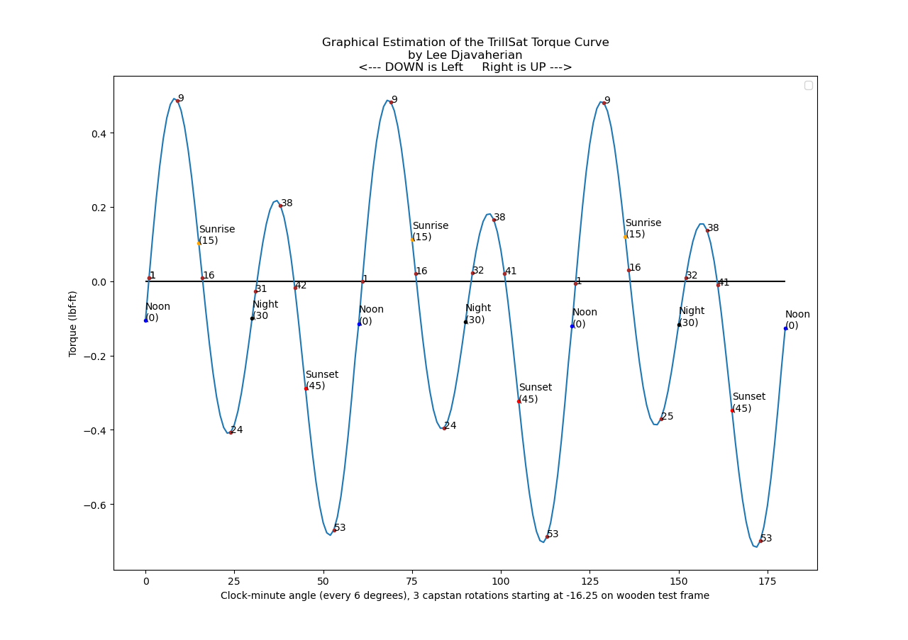
(Click diagram to enlarge)
There, you can see that the hills are very long and steep in the upward direction, especially when the motor is at the bottom of one of those lower valleys lifting both the planetary mass and the craft itself up the sloping tether, and the goal of my equations was to flatten these hills by counteracting the torque, to obtain constant angular speed.
Notice that even angles like 0 degrees, Noon, do not line up exactly at the X-axis (one of the equilibrium points) because, even though the planetary mass is parked at that neutral point and the craft is horizontal, the weight of the craft itself is pulling against the capstan--so the true equilibrium points are slightly offset.
Being like a satellite or spacecraft in orbit, I call this high-level, software-based drive system, the Delta-v Drive System, analogous to a Delta-v thruster burn by orbiting spacecraft, and that's exactly what it does, but instead of performing a constant force for varying times, it performs a sequence of fixed-time burns (electrical motor current) that vary in strength in rapid succession to both orient the craft and change its position within that orbit.
It forms one of 6 layers in the motor drive system hierarchy for TrillSat, which are as follows:
- The Solar-Tracking system, which utilizes an accelerometer and two CdS sensors, to tell the Ramp and Delta-v system where to move for effective alignment
- The Ramp, or smooth start and stop system, which minimizes stress on the frame and motor gearbox and reduces tether sway by calculating ramps based on derived Delta-v torque values
- The Delta-v System (dead-reckoning time-and-distance using mathematics of vector forces, two Hall-effect switches, and two shaft magnets, and real-time I2C streaming to the PWM system at the right times, kept on track via heuristics)
- The PWM system which uses a 16-bit hardware timer for phase and frequency correct, Locked-Antiphase, Sign-Magnitude Pulse-Width Modulation speed control to adjust the speeds (and torque) sent to the H-Bridge
- The Haptic, Morse code communication system which has to be disabled and re-enabled before any motor movements
- The 2-input, BJT and MOSFET-based H-Bridge with hardware shoot-through protection and rheostatic braking that allows high-current control at almost 8 volts to drive a nominally 6-volt, brushed DC motor and planetary gearbox (a cordless screwdriver), quickly switching current and polarity as needed
The Delta-v system is too complex to run directly on the ATtiny like the PWM and H-Bridge and requires the full power of the Raspberry Pi's ARM processor. It also utilizes the two Hall-effect switches for accurate timing which are imperative to correct for error, but more importantly, they trigger data block loads of torque values, what I call "chunks" if the craft was to keep moving through more than one rotation (such as descending to allow smartphone charging and then climbing up again). Due to the high tolerance (high error) of these two 90-degree offset sensors in conjunction with two 90-degree offset magnets, it turns out that the the positions of rotation are not 3 inaccurate tridants but, if edge detection is considered, are better represented as 6 very-accurate sextants, which aren't pure 60-degree sextants but are what I call "zones" with an approximate 1:2:6 size ratio between the zones, like 6 pizza slices of different sizes. The actual size of each slice is not as important as the fact that the edge detection is accurate and that each slice cover the 3 tridant boundaries of 0, 90, and 270 degrees.
After seeing those torque "hills" in front of me for the first time, I realized that I might be able to "flatten" them and started designing an experimental camstan, and this Delta-v system could then work with any offsets between the original torque curve and the smaller curve produced by the camstan (a subtraction between the two curves), perhaps making it easier for this drive system to respond and stay on track.
Math Pre-Generation and Real-Time Streaming
It took me 70 pages of scribbled algebraic notation involving trigonometry and inverse elliptic integrals to derive the equations of motion for TrillSat, and I started working on my first scholarly paper to specifically describe the mathematical aspects (which is the most complex math that I've ever done since my college Calculus days decades ago). Generating the floating point torque values from the math is also complex and done in Python 3 using the SciPy library on the Pi Zero W, which takes a lot of time for around 1 million complex calculations, and I also used matplotlib and NumPy for graphical visualizations on another PC, and these torque values are then scaled and pre-generated into integer torque tables in stages, but at the time a burn takes place, data must be streamed in real-time from the Pi over I2C to ATtiny Sawyer to control the motor since the motor continues to run (through as many revolutions as needed) and quickly change speeds 60 times per revolution (every 6 degrees), and the 8 MHz, 8-bit ATtiny is too slow to perform those computations in real-time to keep up with the moving shaft, and it can't keep the information in memory either, as it only has 1024 bytes total RAM, much of it already in use.
So, at roughly every 180 degrees, at the day/night boundaries, the Hall-effect sensor zone edges for the 90 degree Sunrise and 270 degree Sunset positions inform Sawyer to request another chunk of data from the Pi, which is stored in alternating halves of an I2C byte array, which I call a "block", an array that can only store enough for 1 rotation (120 bytes for 60 16-bit torque values) around 1/10th of the total RAM of the ATtiny. The ATtiny loops through this array, and when it enters a new half, the half it was just on is loaded into memory. I actually have to write 160 bytes at a time to the I2C array since the first 40 bytes are used for my commands and system status, and I couldn't put those bytes at the end of the array since most of the time, I'm not using the Delta-v system and am just performing commands or status and don't want to read/write a needless 120 byte sequence each time. My I2C system is sequential and not random access, but I could incorporate random access at a later time if needed.
It gets quite confusing scaling rotations from 0 - 3599 angles to 0 - 359 angles or to 0 - 60 angles, and then applying start and stop offsets of these angles across many rotations, when the offsets can cross the 0 boundary and vary their starting value with direction of rotation, 270 degrees being the origin for the up direction, 90 degrees being the origin for the down direction. The rotational nature of the angles has to be serialized into a linear sequence, a software version of what occurs in a mechanical crankshaft, and any changes or correction to that sequence then have to be converted back into those angles, the same confusion that occurs in computer time-keeping systems, like the very useful Unix Epoch↗ that almost mimics my own lifespan. I end up using integer division and modulo operations↗ a lot, and this gets even more confusing when each angle has an associated 16-bit torque value that has to be further serialized into byte strings.
Phase Lock and Flow Control
If a Hall-effect switch detects an error in position, it adjusts back to the correct torque value at that position and continues, keeping the shaft phase locked with the motor values. Since this correction can also interfere with phase lock of the data chunks being sent from the Pi, using the Hall-effect switch for flow control to confirm that the shaft has entered the next half is paramount, and dead-reckoning cannot be used here or the wrong data could be loaded at the wrong times. For example, if the motor was running too slowly, the craft might think the shaft crossed the day/night boundary when it actually didn't, prompting a reload, causing the next rotation's values to be suddenly loaded atop the values in use, getting everything out of sync. So the sensor-based flow control is a must.
For 4 years, I was using a buggy I2C routine that cycled over and over until the data finally got through at pseudorandom intervals, causing delays, interfering with interrupts in progress, erroneously executing functions in duplicate, milliseconds apart, without notice, and interfering with the Pi clock-stretching bug (which I thought I had bypassed with my job queuing function). I didn't need I2C to such precision before, as I wasn't streaming complex math values in real-time nor requiring time-critical flow control, but due to the new streaming and phase-lock system, I had to spend months to track down and fix the I2C problems, rewriting my ATtiny, Pi, and ESP code to obtain the required reliability and accuracy.
There is also phase lock occurring with the motion of the sun itself, which is used by its solar tracking system, the top-most layer of this drive system. And compensation for mechanical gear-slack (more on this below) also creates large corrections that have to be carefully handled so that they don't break this phase lock.
Dynamic Debouncing (Noise Rejection and Hysteresis)
Three of the Hall-effect switch zones are determinate and the zone is positively confirmed, but three are indeterminate, what I call INBETWEEN zones and have to be deduced once the motor is in motion at a particular direction, as the zones are arranged in a set order.
Yet due to the interlacing of these three indeterminate zones (where a known one is sandwiched between two "inbetween" ones), switch bouncing at the zone edges occurs which causes the algorithm to erroneously skip over that zone, so switch debouncing timing routines had to be added, but this was tricky since the bouncing period was inversely proportional to the instantaneous angular speed (slower rotations allowed more time to bounce). I call it bouncing, but it's really not mechanical switch bouncing, as the Hall-effect switch generates a noisy output near the transition zones in my arrangement, yet I can treat it the same way as bouncing.
A period that is too short would cause bouncing to occur, and too long would cause the Hall-effect switch to miss the next true zone edge, so dynamic debouncing had to be added based on the speed of rotation. So in addition to the dynamic delay, I also had to apply a weighted multiplier based on that 1:2:6 ratio to adjust to the width of the slice, for the longer slices could tolerate a longer delay and still be reliable.
The delay affects the changes in motor current too, not just the hall sensing, which seems disadvantageous as I want the motor to continue on dynamically yet only deactivate the sensing, but since a debounce only occurs right after a zone transition, there is an auto-speed correction that occurs (more on this below) that negates any accuracy obtained by retaining the values, and those values also contain different torque values (different speeds) which interfere with the speed-sensitive debouncing. For example, if a zone edge was detected, the debounce goes into effect for the last speed leaving that edge and holds the delay at that value. A new torque value might be stepped significantly lower or higher due to the correction, widely changing the debounce delay, corrupting the speed-based debouncing system.
I tried to use hysteresis to correct for bouncing errors, but the indeterminate interlacing became a problem. While the 4 zones are directly-confirmed, in comparison with the 6 phases, the In-between zone is directly confirmed to be... indeterminate. All I know is that it must be either Morning, Afternoon, or Night. Due to this interlacing, however, the worst-case scenario occurs in that I cannot use a memory of my 6 phases to rule out bouncing, for they are indirectly-confirmed. In other words, if the motor goes from Morning to Sunrise to Night, the system doesn't know for sure if it bounced from Morning to Sunrise to Morning, since all it really sees is In-between, Sunrise, and In-between; I cannot apply effective hysteresis here.
Testing a Jovian Spaceship on Earth
Other than finding and resolving my own software bugs and performing those orbital dynamics math calculations, the most difficult part of designing this Delta-v system is the fact that I cannot get accurate feedback from the unit to determine if my algorithm is working for the sheer fact that the craft in actual use will be under a dynamic, changing load. On a table with the motor free to spin, these dynamic forces are not available.
The speed-based component of the dynamic debouncing system, while great for testing on a table when the motor spins at different speeds (constant load, dynamic speed) is useless in real-world testing (dynamic load, constant speed), and luckily I can still rely on those size ratios, as ideally, the angular speed should not vary, for that is why I went thought all of the trouble to derive those motion equations and dynamically alter the motor current in the first place.
I also can not test my mechanical gear-slack compensation on a table, since the tether takes up the slack in different ways.
It reminds me of the problem when scientists capture deep sea creatures and bring them to the surface for testing; the creature is often destroyed and its true representation is lost due to both the lack of pressure and the lack of water as a support structure. If one were to design spacecraft to descend into the dense atmosphere of Jupiter on the much less dense Earth, we would encounter a similar problem in building it. Surely the Galileo probe engineers and the Venera engineers confronted this, for tiny, earth-sized Venus has a tremendous atmospheric density.
Creating an apparatus to mimic those larger forces for me is more complex and difficult than simply setting it up on the tether, and doing so would cause weeks of unwanted mechanical stress on the system just to test my abstract software, so I had to find ways of mapping the problem into another domain so that I could interpret and translate the feedback back to the original problem. Creating a computer simulation to generate those dynamic forces is out of the question, too, for if I had such precise math values to create that simulation, then I could simply apply those values to the craft and be done with it--no need for the simulation, a catch-22. What I did create, though, was a table of idealized torque values for the tether down to .1 degree resolution or about 16 micrometers linear distance for its smallest burn, minus the momentum calculations.
Momentum is an entirely different issue, something too complex for me to incorporate into my already complex equations, especially if the tether starts moving around. The 1 lb planetary mass, if moving quickly, has enormous momentum which can negate my careful torque calculations, like handing a bowling ball to a spinning figure skater. But if moving slowly, which it was originally designed to do, the momentum has less effect and my hope is that it will be just low enough to work.
I cannot test the momentum effects on a table but have to put it on the tether, and I have to obtain many calibration values on the tether that are different than those on the table. But since the Delta-v system uses a fixed time and then varies the speed to tune the craft to the tether, my slower speeds (with longer time values) require less PWM current which both lowers the resolution and causes the torque to drop off when I need it, and the motor can't move the planetary mass up the steepest regions. So, even though my math equations show the necessary torque, that doesn't mean that it is available under the software limitations unless I drive the thing fast. Technically, with DC motors, maximum torque occurs at the lowest speed, but this implies that the duty cycle is also maximized which could drive the craft fast in places where my idealized torque curve does not match up to real-world conditions.
And driving the thing faster than I would like for a craft heavier than I would like means that it increases momentum. It's a scary procedure that can risk damage to the fragile craft as it whips around erratically until that calibration value is found, as if a mechanic was tuning a car's transmission while the car was being raced on hilly roads. The field of robotics can get just about as complex as any other science/engineering field, depending on how far you want to take it, but I was hoping to skirt by some of these difficulties by using more simplistic, wheeled mechanisms and not multi-jointed appendages. However, because of the axes of motion, and the precise movements that I require, I unwittingly created something similar, but in rotational form.
Of course, engineers of real spacecraft often have budgets large enough to design those complex, earth-based testing systems since they can't just erect a tether into a tree, and I should consider myself lucky. As I write this section of the page in September of 2020, the first Martian robotic helicopter↗ is enroute to Mars and they won't know for sure if it will fly but they hopefully obtained enough information to make this a strong possibility.
While my dynamic debouncing is one testing casualty, another problem is the fact that, on a tether with a low radius of curvature and with craft kinematics that repeat themselves every rotation, the torques needed for each rotation are very similar, only changing gradually over time as the slope of the tether changes. They are so similar that I cannot audibly or visually tell the difference, and since the ATtiny loops through the I2C array over and over, I cannot tell if new data is being properly loaded into the correct day/night chunks. The data streaming could come to a halt and I'd never know since the system would loop over the same data, acting almost the same way (which occurred in testing). So I had to inject "bad" data into the stream in certain chucks just to get some sort of indication that it was working and was in phase, but even this was hard to tell since the motor doesn't act normally during testing on a table anyway.
This is because, when I fire up the equations and perform my burn on a table, the motor rotates at varying speeds since the current is changing every 6 degrees, but on a tether it should rotate at a constant speed, countering the opposing dynamic torques that it encounters. The algorithm and time-and-distance equations were designed to expect this constant speed and adjust for phase lock, but the dynamic speeds of the table-based tests throw this all off and the motor stutters and speeds up as the feedback correction tries to compensate, and the expected distances are thrown off since the speeds are off, etc.
Finding the Torque Offset
I was able to create a constant-torque testing function to override the dynamic torque values with fixed ones to test the Hall-effect sensing and correction system while on a table.
But on the tether, when I perform a Delta-v burn, I provide my algorithm with a set distance and set time and it computes (or has pre-computed) the dynamic speeds needed to traverse that force-changing distance along the tether to arrive at that specific time. However, I don't know the actual electrical current needed to produce the motor torque (which should be proportional under PWM) so I first have to perform a calibration to obtain this value. To do this, all Hall-effect phase-lock feedback correction must be turned off, leaving only Hall-effect sensing enabled, and a single rotation is activated and timed. If it ends too early or too late and doesn't complete exactly 1 rotation, then the current (speed value) is manually adjusted until it does.
On a table, I can automate this for constant-speed testing but cannot find the value for the actual tether, since the speeds are dynamic, throwing off the distance, driving it much too far. So the calibration can only be done on the tether and the mass will stall or whip around violently until this value is obtained. Once this value is obtained, it should no longer be used to change the speed of the craft and any future changes to the speed should be done only through time-and-distance values sent to the Delta-v system, which changes speed accordingly.
It's a type of two variable tweaking and fine-tuning that is somewhat reminiscent of setting record/playback levels in computer software to obtain a high-quality result. I did encounter something similar when setting volume/deviation in my FM-based PacketRadio system and it's a curious thing that I don't encounter very often in my digital projects unless they interface with the natural world in some way. So even though I have two ways to change motor current, I think of the coarse tuning as Torque and the fine tuning as Speed.
Maximizing Dead-Reckoning Precision
A dead-reckoning maneuver is a form of open feedforward↗ control, where you have to be very careful of cumulative error. I've been fascinated with it for some time, as it shows the causal, clockwork precision of the Universe around us, the type often demonstrated in our spacecraft. Charles Lindbergh and Christopher Columbus both used it to cross the Atlantic, but the Ancient Chinese South-Pointing Chariot used by the Yellow Emperor in the mythical Battle of Zhuolu↗ has long been my favorite example.
But it becomes useless if you have too much cumulative error, so the precision of every element involved in the control system has to be scrutinized and maximized, otherwise the accuracy suffers and it it becomes just another malfunctioning spacecraft burning up in the atmosphere or shooting off into the void of deep space. Before adding this Delta-v system, I didn't have to worry about this, and for ease of programming, I used lower-resolution units of time, lower-resolution units of electrical current, and lower-resolution Hall-effect angle sensing (as I didn't even incorporate the edges of the zones), and did not account for mechanical gear slack, static friction, or assembly misalignment. The Hall-effect switches added some closed-loop control, but any movement between the sensors is still dead-reckoning. The closed-loop control can be turned off, however, only using the sensors for flow control of the streaming data and not orbit correction, something I find very exciting, allowing it to drive on pure dead reckoning at any distance.
I was also scaling by adding offsets to slower speed values, removing some of my significant digits when I should have applied percentages to the highest speeds, chopping them down and preserving those digits.
The mathematics of the motion is unforgiving, as demonstrated by my first failed tests, and so all of this had to be corrected to maximize precision. I moved the timer down to .5 ms resolution, the electrical current moved to 10-bit 1024 values, and the edges of the Hall-sensors were incorporated. The system also switches between Sign-Magnitude (10-bit) and Locked-Antiphase (9-bit) modes automatically during the rotation, depending on the torque values, as Locked-Antiphase prevents gravity from accelerating the mass too quickly, adding a braking effect.
The Lithium-ion battery voltage also drops over time which I noticed audibly in testing, which affects current, which affects angular speed and torque, and I never thought I would need to use the series-mode battery voltage sensing of my ESP8266 ADC high-impedance voltage-divider circuit (which was mainly a redundancy item to make use of that unused ADC) to read the voltage while the motor is under load--this is an interesting data point that I hadn't considered and changes dynamically as the load (and current) changes. It is a source of significant error that allows the craft to deviate from my torque curve, and so I did some fascinating calculations in April 2021 to hopefully compensate for this issue, which I plan to add to the algorithm later.
I didn't design TrillSat to be a precision system, just an efficient one, and while I foresaw many of the mechanical and electrical parameters that I needed, I did not think that I would need a "collection" of these particular ones to be within such ranges, but the Delta-v system is reliant on several variables, and the weakest link in the collection causes huge cumulative errors. Again, I designed something more akin to a wobbly mobile home to match a different kind of efficiency, not a precision racecar, but those mobile homes are also curiously similar to spacecraft.
Each wobble in my wobbly craft had to be identified and corrected to maintain alignment with my idealized mathematics, and what I found was fascinating: While some areas of the design were obviously lax and had huge tolerance zones (something I knew when designing but hoped would still be within the required useful range), other seemingly lax areas were extremely precise.
This precision is needed for two things, to improve the accuracy of the time-and-distance dead-reckoning of the motor when under open-loop control for generating the right motor torques at the right time for smooth, constant speed and, and just as importantly, to obtain accurate solar alignment, for the shaft position is non-linearly proportional to the position in the sky that the plane of the solar panel is facing. If you know where the Sun is, then you need to be able to point the panel at it.
I've got an accelerometer and two CdS photoresistors which can assist and provide confirmation, but that doesn't help much when the craft is in motion and swinging all around on the tether, so accurate dead-reckoning is important to get it right on the initial tries.
To me, TrillSat is an analog of spacecraft and satellites, and one of the unique things about such crafts, like Delta-v burns, is the precision use of Keplerian clockwork and Newtonian mechanics, rotational perfection fit for the Jovian spacecraft in 2001: A Space Odyssey and I want the craft to predict its idealized future, where it "should" be if it followed mathematical "law". The craft is primarily an idealization that I'm trying to bring into the real world, even if it may not live up to that symbol in practice, as I did have to reluctantly add minimal levels of sensing and heuristics for practicality.
Motor Boost Heuristic
When the phase lock is engaged, as mentioned above, with the Hall-effect switches sensing the motor shaft position and performing correction to keep it on track with actual motor torque values, there is the case when the motor runs too slowly and does not reach the sensor by the appropriate time, either being stalled, or more likely running too slowly. Even with accurate calibration values, the real world system on the tether will not exactly match the mathematics and will either be too slow or too fast during its 6 dead-reckoning phases per rotation. If it is too fast, it just abruptly switches to the correct torque value for that position, but if too slow, I decided to perform a stepped, acceleration "boost", gradually increasing speeds every 6-degrees (assumed) until it reaches its destination, assuming a stall condition and shutting down after a certain time.
But keeping it at the speed that created the slow situation in the first place is obviously not ideal, so a step up is an improvement. The motor might have been going so slow at that point that continuing that slow speed would delay or infinitely stall the motor (if a hill is approaching). If the hill is large, the motor is like a driver that keeps pushing down the gas pedal until it climbs up again. Obviously, the original time to reach destination will be exceeded once it catches up to a sensor and is re-adjusted to correct speed, but, unlike the individual burn times, the total time values are not important for TrillSat, only the distances and speed traveled, as there is nothing time-critical in the locomotion phase other than the solar movement that the tracker must follow, and while fast, it's not that fast.
The system then adds a correction value depending on how slow or fast the error (proportional to the percentage of error) and continues, another system which I call "speed correction", becoming more accurate on the next loop. This might correct in cases where temperature and weather affect the craft.
Hall-Effect Switch Auto-Calibration System
When I first noticed the extreme tolerance in the 3 Hall-effect tridants, large enough to consider a "zone", and decided to track the edges, I was very excited about this failure that magically became a benefit and excitedly got out a tiny protractor and measured the edges of the 6 sextants, but after testing my "too slow/too fast" system on a table in my constant speed mode, I noticed that the sensors weren't lining up--even under constant speed some were too slow, others were too fast. So I knew that my measurements were off and created an auto-calibration system that utilizes the motor and Hall-effect switch edge precision to find the following precise values automatically:
- The 6 angles of Hall-effect zone edges
- The mechanical gear slack when the motor changes direction
- The assembly error of the magnet holder on the hex bit
- The static friction of the motor
The last three are simple offset constants, but they turned out to be very valuable for dead-reckoning as well.
To get the angles, the computer times one rotation and then determines the percentage of that time value at the different sensor points to find out where they are (since the angular speed should be constant at constant current). It does it for both directions and stores the 12 values in EEPROM which are read quickly in the future (since EEPROM reads are pretty fast in comparison to writes), and this saves a little bit of RAM, too, but since I program the chip repeatedly during testing, those EEPROM values are lost, erased to 0xFF, and I had to temporarily check for erasure and use additional memory to insert safe defaults to eliminated repeated calibrations.
It turns out that these angles are very accurate, matching in both directions, and there is very little difference even if the speeds are increased, or the type of PWM varies, due to the speed and precision of the Hall-effect switches, the precision of the timers, and the fact that the motor spins at a constant speed.
And then there is the case of assembly error. When the planetary assembly is attached to the drive motor, it uses a steel hex bit, and hexagons have 30 degrees per side, which means if the magnet holder ring is not aligned with the hex bit, which is aligned with the planetary rod angle, there can be a maximum of 15 degree error here. I tried to line this up by eye, but at such small diameters, the error is hard to see. Using that same test capstan and hollow planetary rod, I can also tell the motor to drive until the tube reaches a center mark on the planetary space pod (which should be exactly 180 degrees) and if the system is off, either manually measure and enter the offset, or increase/decrease this value until the mark is found, which shows the assembly offset. So as long as assembly is close, the calibration can find an even closer value.
One last piece of assembly error is the the mounting of the motor to the gondola, that the molded ABS screwdriver handle does not fit tightly within the rectangular void, and I've often crammed hexagonal pencil pieces in the corners to keep it tight with no slack. I may one day print a slightly smaller mold of this cavity and use epoxy to create a rectangular base around the molded handle to fit securely into the rectangular cavity.
The motor doesn't actually move when engaged, as it has to overcome its own static friction before it starts moving, so I have to also find this offset and start from that offset instead or it will also skew my time-and-distance measurements (especially with the ramp system below) and this friction varies depending on the load and whether it is on the table or on the tether.
Using this same calibration system, the motor drives slowly in the up direction to the Morning position were the force is very low, then in stepped attempts, it tries driving in down direction away from that position back to the Noon zone, the first value that gets it to move is the static friction offset.
But when the motor changes direction, there is a slack of a few degrees in the gears. So I placed a test capstan and drove the motor drive fairly fast one rotation, then abruptly changed direction (causing the gears to take up their slack) and return to the starting point. A rod could also be added to create a little eccentric mass to the capstan to add some momentum to aid in pushing back the gear slack. The percentage of time difference is used to find the degrees of error, and this is stored as an offset value. This offset value has to be applied whenever the forces on the capstan switch direction (or its perceived position will be off) which is usually when the torque changes from positive to negative or vice-versa causing the planetary mass to fall to the opposing side, like on a roller coaster when the people in the first car go over the top of a hill and fall forward until the craft starts moving again. Luckily, I know these polarity reversal points, as they are defined in my equations.
But since I also know the static friction for the table (under no load) and can later obtain the static friction for the tether under load, which is much higher, when the tether is erected on the tether, I can engage the motor at a value between these two numbers and the motor will take up the gear slack, yet the craft won't move. This is needed anytime gear slack cannot be ruled out during start up conditions.
The Ramp System
My math torque equations also do not consider another practical requirement, that, once slack is removed, instantaneous speed changes and lack of smooth starts and stops add stress to the system. Some of the stress is relieved by my ball damper inside the planetary mass, but I really needed those smooth starts and stops back. The problem is that applying my old ramp function interfered with these new mathematical time-and-distance equations, so I had to layer the ramp function atop the Delta-v system, not the other way around. It's curious how such a primitive, low level construct rose to such a high, abstract level.
The TROT system, the two kinematically-connected locomotion and solar panel tracking systems, requires that the distance along the tether be unusually precise for such a crude motor-drive system (a geared, brushed DC cordless screwdriver motor). There is no stepper and no BLDC (like there is for my Gyro system that ironically has a precision of 36 steps per revolution but I don't even need it).
Since a burn is simply a series of fixed-time, 6-degree segments of motion at varying torques, if the burn is the first or the last, I can substitute it with my ramp function. In order to make sure that the motor moves the same distance, I had to use the relationship between the triangle and rectangle, in that a triangle of the same height must be twice as long to contain the same area as a rectangle, the area being representative of total motor speed over time (distance), so even though powering the motor using a triangle waveform takes twice as long, the motor moves the same distance. The ramp up function skews my time values, which have to be compensated for if the motor will cross sensors, but there is so much error at startup (which is correct later during motion as it passes the sensors) that it isn't too much of a problem. What turns out to be more of a problem is the fact that the motor doesn't actually move when the ramp is fist engaged, as it has to overcome its own static friction before it starts moving, so I have to reset 0 to that static friction offset that I obtained earlier.
The ramp only reaches the torque value of that burn section before moving to the other burns in the sequence, so ramps of different starting positions have different slopes, so on a table, under constant load (no load), slower speeds have more gradual ramps and faster ones have rapid ramps, but on a tether, when the speeds are negated by the dynamic torques incurred, the effective slopes should be the same.
There is an issue with ramp downs, though. Exactly 10% of my angular positions cannot perform a ramp down, for they trigger the 6 Hall-effect edges, and the system could determine that it is running too slow and then boost the speed to reach the sensor, but it if ramps down, such a boost would cause a stop/start condition, destabilizing the long-term burn. But the other 90% of the time, the system doesn't known any better so a ramp down is not detrimental and is preferable.
Clock-Minutes and Clock-Seconds: Finite and Impulse Burns
I didn't use a 360-degree precision but chose one 10 times finer, a precision of 3600 degrees per rotation, or .1 degree, which matches the max resolution of my accelerometer readings. But since it takes the ARMv6h Pi Zero W in Python 3 around 76 hours to generate the torque values for a 50-foot (15.24 meter) tether, I first have the craft pre-compute the torque tables for the entire tether for only 6-degree precision (which only takes 76 minutes to generate) which I call "60 clock-minutes" just like the 0-59 marks on a clock-face minute hand. It has to generate these values anytime the tether length, tension, or height are changed, which changes the mathematics involved. It is ideal to compute the whole thing in advance, for this gives me the option of free locomotion, moving anywhere on the tether and knowing where I am (with the limitation of being within 6-degree resolution, around 1 mm linear length).
Once this position is achieved, further refinement by 60 more angles (.1 degree resolution) can be performed to obtain more accurate position, a type of progressive refinement, like a type of level of detail in graphical rendering. The craft moves to a rough clock-minute position via a Delta-v burn, and then it performs a tiny clock-second burn without any sensor feedback or motor streaming (since it fits into the 60-angles that the I2C array can hold at one time), stabilizes, and the accelerometer determines final error. Additional clock-second burns can then be performed to tune to final position.
The clock-minute burn is a form of longer-distance navigation which can span any number of rotations up and down the tether, real-time locomotion, analogous to a "finite burn" in spacecraft orbital maneuvers. The clock-second burn is a single burst (albeit a complex one with up to 60 tiny, mini-bursts), analogous to an instantaneous or "impulse burn" in orbital maneuvers↗. Even though both are really finite burns underneath, I treat the clock-seconds in my software abstractions as a single unit, since I consider the 6-degree clock-minute being the standard unit for a "burn", and similarly, in orbital mechanics, instantaneous burns are not really instantaneous, but are physically varied underneath but just treated that way as an engineering abstraction.
In addition to the confusing nature of using rotational angle values to describe a linear sequence as I mentioned above, there is also the confusing nature of angles themselves. A clock-face is like a compass in many ways↗, since both are related to solar patterns, yet the terminology and details are slightly different.
The 3600-arc resolution acts like seconds if they were applied to a clock and not degrees or arcminutes on a compass, which is why I prefix my angle terms with the word "clock", like "clock-minute" to differentiate. Coincidentally, 10 times the number of degrees in a circle, which I need to reach .1 resolution to match my accelerometer, is the same as the number of seconds in 60 minutes; it's odd how this worked out.
The 60 clock-minutes are not quite twice the resolution of a 32-point compass. Even though TrillSat is oriented toward cardinal directions, the use of the clock-like base 60 instead of compass points helps me intuitively know where the mass is, while also being a 6x multiple of a degree to ease my math calculations. So in my setup, a clock position of 6 minutes is 36 degrees, a clock position of 57 minutes is 342 degrees, etc.
The curious base 60 system, or sexagesimal↗ has always fascinated me. I've long been interested in ancient, advanced civilizations, and the fact that the Ancient Sumerians were so old, yet so advanced draws my attention. Before Sumer and the Epic of Gilgamesh, we essentially have prehistoric times.
The clock-second impulse burns do not have ramping enabled at this time as they should be as slow as possible to take stress off of the drive system (and the distances are very small), and it is unknown if the additional resolution will have any real-world benefit on the tether (unstable static friction will likely negate most of this precision), but it will at least move the shaft a short distance (usually 6 degrees or less) which can then be measured by the accelerometer to improve solar angle alignment. Even very small angles of misalignment can have a surprisingly large effect on solar panel efficiency.
One note about the accelerometer--even though it has the same .1 angle resolution as my motor drive system, the solar panel angle has its own non-linear scale that doesn't quite match the linear distance relationship of the capstan drive. This relationship was also tricky to obtain, for while I can mathematically find the solar panel angle from knowing the capstan angle, I cannot do the reverse, since there are many capstan positions along the tether that produce those same angles. So I just restricted the domain to one revolution and pre-computed a table that I use to perform the reverse lookup.
On the wooden test frame, at the greatest tilt angles, the panel might not tilt more than .1 degree every 30+ .1 degrees of capstan rotation, but when almost level, the panel might tilt almost .3 degrees for every .1 degree of capstan rotation. So there will be times when the accelerometer can only get me within 3 degrees of distance accuracy and other times when it can get me greater than .1 degree distance accuracy, or under .2 mm precision, something only beneficial to me for staying close to my idealized, dead-reckoning orbit, but either way, it is still more than accurate enough to get me within a clock-minute of my intended location to know where the craft is in space.
When a clock-second impulse burn occurs, to save RAM, it reuses the same array to store the 60 16-bit torque values per rotation and they all fit perfectly (in 120 bytes) without requiring any I2C chunk streaming. It's analogous to how the minute hand and second hand (and even the hour hand) on a clock use the same clock face↗ for spatial efficiency, a type of multiplexing, a fascinating philosophical insight, like sexagesimal, that I never thought much about.
Racing the Sun
At summer solstice in my area, the Sun rises to about 74.8 degrees at solar noon (zenith), with around 14:52 minutes of daylight, around 6 minutes per degree (on average only) which is quite fast and almost fast enough to outpace any real-time computations of the torque angles needed to match it. My South Pointing Space Chariot is trying to race a Sun Chariot↗.
What I concluded was that, in actual use, I would only be concerned with those top two daylight tridants, 180 degrees, once per day, and during the larger, night tridant, I have many hours with no movement. So I decided that when the craft is pointing to the noon sun when solar power is at maximum, it pre-computes the 1800 angle values needed down to clock-second resolution for the next day, stored as a "trillsat_secondstorque[rotation#]" file, which only takes around 5 minutes to generate and the stored battery power for the day should be available to do the job if needed, but this computation reverses direction at the winter and summer solstices. In the spring, for example, the craft moves lower and lower on the tether to match the angle, and in the fall, the craft moves higher and higher.
This means that I need to not only pre-compute that torque table, but I also need to pre-compute a tangent angle table (essentially the derivative of the tether) so that I can quickly know when the next day should move up or down the tether, one rotation. So before the next day, it will first calculate where it will go next, then pre-compute the daily_clockseconds file for the day. In this case the array handling was much easier than my reciprocating-chunk I2C streaming, and simply stored the short burn sequence that was generated by the Pi Python code.
On a 50-foot tether, there are 269.5 rotations along its length, even less than this that will be within the range of solar alignment, but there are 183 days in half a year (a closer integer approximation if you consider leap years), so it is possible that an up/down movement to match earth tilt could occur daily, so I have to compare the daily elevation angle at zenith for my latitude with the table that I compute and then move the craft as needed.
These rotations are like digital stepped or quantized zones, and luckily, the tangent table is easy to compute, as I've already defined the curve in my equations, so I compute it just like I compute the torque table.
From winter solstice to summer solstice, the craft has an easy time if the solar angle prompts a daily move, with no need to "re-park" at sunrise but to just naturally move to sunrise. But for summer solstice to winter solstice, the craft is going uphill, and at sunset, the mass has to have enough momentum to pull it over the steepest hill, so the park method as described in my previous Three-Tridant heuristic drive system may still be needed to generate momentum if the calibrated torque equations are not enough. Torque is like that impulse burn, that instantaneous force, but momentum is more like a finite burn with a memory; it has a history, being related to mass, energy and velocity, and can accumulate excess energy like a battery, being "charged up" via mechanical work↗ by those torques from a previous time to impart at a future time when needed, but just like those finite burns... it gets complicated.
Each day before reparking, the Pi will send the 120 clock-minute torque bytes needed for the next day's rotation to be stored into bytes 135-255 of the 256-byte EEPROM of the motor driver ATtiny (Sawyer), which allows the system to completely power down at night if it runs low on battery power, and in the morning, when the Sun arrives, only power up the two ATtinys. Sawyer, on its own, in conjunction with the Hall-effect and CdS sensors, can then move the entire craft into rough clock-minute position without much trouble to track the Sun so that Huckleberry, the power regulation ATtiny, can charge the batteries and/or enable the ESP (which can then enable the Pi). Even if the Pi cannot be brought up again that day, Sawyer has enough information to repeat that maneuver for the next day, only dropping slightly in efficiency. Without these values, Sawyer would not know how to drive the craft smoothly on its own.
The mechanical gear slack, assembly error, and static friction, offsets are stored in Sawyer's EEPROM as well. The motor speed correction factor is not stored in the non-volatile EEPROM at this time.
The Powerful PBBS
This is really the core of the system and the reason for everything else. The PBBS, or Packet BBS (Bulletin Board System), is simply an interactive computer terminal over packet radio, like a crude version of a Kiosk or even a modern, AJAX-style web page. It can be anything really, as it is a portal into any conceivable software program. The most sophisticated AI in the world could reside behind one, or it could be as simple as small message board. But don't expect it to be pretty. It is just simple text.
But text is powerful and conveys meaning, one of the most profound and mysterious things in the Universe.
Notwithstanding FCC Part 97 regulations, there are no real restrictions here. Like how a good writer can create any world imaginable, it is capable of doing just about anything you can think up, only limited by your creativity and intelligence. Of course, creating something that is beneficial to other hams is a plus, as spectrum is limited, so contributing to the "basis and purpose" of amateur radio is important.
Writing a PBBS in Python is not as simple as it seems, and there aren't many written in this language.
In the old days, there was a Linux program called PMS that created a store-and-forward packet mailbox, in a collection called ax25-utils, but ax25-utils was removed from all modern distributions years ago, being replaced by ax25-apps and ax25-tools. Most of the programs were carried over, but PMS was dropped... It is difficult to find online and there is very little information on it. I tried to get the C source to compile, but couldn't, as it seems that it was written for an older kernel and it would need to be heavily modified first.
There are some old PBBS programs that people have recently gotten running on a Raspberry Pi, Pi 2 or 3, but it is hard to get the source to compile on most of them, and they are complex. Many of them were written in C, and many were written for Windows machines. I like C, but I didn't want to write a PBBS in C when Python was available.
At the time of this writing, the PBBS performs the following functions:
- Live chat with the station operator
- Leave a message for the station operator
- Deliver a message to the remote station
- Send a text to a remote station (just like a phone text)
- Provide information about the system
Thanks to AX.25, it allows the connection of multiple users simultaneously, but these users can also interact with the station operator, and vice-versa, to some extent, a neat feature.
However, it also does something unique for single transceiver, especially a UV-5R series radio. It can send out custom APRS status report messages on a completely different frequency at periodic intervals. This status report can include information about the PBBS listening on the other frequency, the number of users connected, and other information such as the Maidenhead grid square location. And this APRS message can also be sent while other AX.25 packet sessions are in progress on the other frequency. It quickly performs this function, minimizing any interruption, using a variety of techniques explained later.
So, for example, the station operator can be sitting at home and suddenly receives a notice on his smartphone that another ham left a message for him, or even wants to chat with him. The operator can just text back to them using Xabber, just like sending an SMS text, and carry out a conversation. The station operator never has to use a desktop computer or touch a ham radio to do this, and no Internet connection or AC electrical power source is required.
The craft robotics can also report back the state of the craft and its sensor readings, providing a neat teaching tool for hams in the area, like communicating with a "local" spacecraft.
The Smartphone Meets Packet Radio
This is where it gets even more fun. Instead of using a smartphone to send out SMS, or use XMPP or a proprietary messaging app to send text over the Internet, that same smartphone can be used to send out a packet radio "text", completely bypassing any cell or Internet infrastructure. The ax25d daemon listens for connections and when it hears a callsign with a different SSID, it sends a "--mode" argument to the PBBS and the PBBS goes into a different mode where it does some basic handshaking to retrieve the text. On the sender's side, their client communicates with the AX.25 call command to send the text, and the entire transaction takes less than a minute, with the benefit of having return-receipt confirmation.
XMPP and 1200-baud packet radio were made for each other, in my opinion, since they are both very good at sending short text strings. However, they come from two different worlds.
There is a huge communication gap between the heyday of pre-Internet packet in the 1990's and today's hyper-connected world of smartphones, social media, and Web 2.0 technologies. In general, hams (the technical aspect, not the social or contesting aspect) and the recent phenomenon of makers, hackers, etc are almost like 2 parallel worlds trying to achieve similar things without really understanding what the other group is doing. Over the last few years, I visited my first maker/tech conventions and my first ham radio club meetings. At the time of this writing, I'm not a member of either of these groups, and do most of my work as an individual, but visiting them gave me some insight into these worlds.
These gaps have created immense difficulties for me in determining how to build such a system. There were a multitude of articles written by hams in the 1980's-1990's about packet radio, and numerous software programs were written, but they were done by individual contributors (many hosting the information themselves), and as popularity waned at the turn of the millennium when the World Wide Web was rapidly growing, people stopped writing about or maintaining these articles or programs. Search engines will not pull up most of this information--it is either not popular enough or hosted on any servers.
A smartphone is a battery-powered supercomputer that also acts as a communication device, but if the mobile connection or the Internet WiFi connection goes down, it can no longer communicate. But WiFi connections weren't designed solely to connect to the Internet, they were designed to use IP protocol. An ESP8266 can easily act as an IP access point. Without an Internet connection, a smartphone won't get you on the Internet, and without a mobile radio, it won't connect to any cell towers. But a smartphone can use its WiFi connection to connect to a packet radio system to allow "texting" over the radio.
As long as there is a power supply for the smartphone, communication could continue to nearby packet stations indefinitely, which is why the craft also employs wireless Qi docking to allow the smartphone to be re-charged via captured solar energy. Of course, these texts can't be encrypted due to FCC Part 97 regulations, but privacy may not be as important in an emergency.
But the smartphone isn't just for sending texts, it can also send commands to the unit to control its functions, like the control-link on a satellite or remote spacecraft, and these commands can be encrypted. If the unit is in range of WiFi, consumer WiFi has no such FCC restriction on encryption and WPA2 is possible, although the KRACK vulnerability that was made public while I was working on this project is a great example of why we shouldn't blindly rely on such systems.
However, interestingly, control commands over ham radio frequencies can also be adequately performed without encryption, yet still prevent a malicious "replay" attack, by using shared codes that only the sender and recipient know. To the best of my knowledge, based on how I interpret the FCC amateur radio regulations, as long as the meaning of the communication is not obscured, such a code would be valid. A ham just can't insert any secret messages in the codes (encode them), and it is probably a good idea to publicly document this mechanism and/or source code before using it, just so other people can better understand the communication that is taking place. For example, I could send a command "8793797: GO TO SLEEP MODE", and this is clearly a CPU sleep command. The random number doesn't carry any special message, but the receiver program just won't act upon the command if it is invalid, and a new random number is used each time to prevent a replay attack. I could just periodically upload a list of random numbers to the server over the encrypted WiFi network, using them sequentially for each command, and as long as I only use each number once, and the numbers are sufficiently large, it is unlikely that someone could guess a code. Time delays could be added also to slow a brute force attack. I would probably also follow that command with a "SUCCESS" or "BAD CODE" response, which would further clarify the meaning of the code. In other words, without such a response, someone monitoring the airwaves would not know if the code was successful or not, so technically the meaning would then be "obscured", and so a response clarifies this, while having the added benefit of alerting other hams that an attack on the system might be in progress.
Auto Network Failover
I programmed the ESP8266 to use 2 different modes, a normal mode and an emergency mode.
In the normal mode, the ESP connects to a typical home WiFi router as a "client" using DHCP and WPA2 encryption, and on the router, I configured static allocation so that its MAC address always receives the same IP address. The router is also configured with a high DTIM interval which keeps the power usages on the ESP WiFi very low. The ESP connects to the access point surprisingly fast (a few seconds).
This mode is preferred for 2 reasons:
- It is the only mode that allows DTIM low power
- It allows my smartphone to stay connected to my WiFi router and still connect to its Xabber server. Xabber allows one to connect to multiple servers and use them simultaneously, so I can use the same client that I use for other XMPP communication and still receive incoming texts from remote AX.25 callers.
However, if the power grid goes out, the WiFi router, of course, will go down. At this point, I programmed the ESP8266 to create its own WiFi access point, using the same IP address as before. Android will then auto-connect to the new access point instead (if this has been previously setup), although it will complain that there is no Internet access, which is fine, since IP access is all that is needed. After it does this, Xabber will then auto-connect to the XMPP server. By telling Xabber to use a custom server that is an IP address and not a DNS name, it doesn't need to contact a working DNS server (which doesn't exist, since the power went out), and it re-connects to the XMPP server. This allows full operation on battery power without the Internet. The ESP8266 uses more power in access point mode and cannot use DTIM, but this can be mitigated by using other techniques.
In my first design, I relied on the XMPP ping mechanism to determine whether or not the ESP lost connection with the router, which wasn't ideal, so I used the NodeMCU wifi.sta.status() function to check to see if the access point is no longer found.
I also configured the GPIO0 button on the Adafruit Huzzah ESP board I'm using to toggle between these two modes, in case it is nearby in Test Mode with the Radio Box panel open.
Handling Radio Failure
Since there is no virtual UART timeout, as mentioned above, it just hangs if something goes wrong with the radio, which occurs fairly often. Programming the radio is finicky, and sometimes the radio refuses to accept programming. This occurred both in tests I ran on an actual hardware serial port and a virtual serial port created by pigpio. Dire Wolf and pigpiod consume a fairly large chunk of the Pi Zero W CPU ( I had to set them to options to reduce CPU usage), and under interpreted Python using a software UART at 9600 baud, it can barely keep up with the responses from the radio, which is time-critical, even with /boot/config.txt force_turbo=1, so I had to be careful with the order of the programming. I also added an option to limit the maximum number of users on the PBBS to reduce CPU overhead. If there are any upgrades to the OS software, they can affect the timing, as well. The Pi Zero W can also suffer from broken audio pipes in Dire Wolf 1.5 if it cannot keep up, so I had to use the A decoder, as the A+ and E+ were too intensive, and I had to limit everything to a single audio channel, as multiple channels put too much of a load on the CPU. On my TRILLSAT-G ground station which uses a Raspberry Pi 2 and newer UV-5RA with a slightly newer firmware, one of the ACK reads that works fine on the Pi Zero and older UV-5RA will not read and had to by bypassed. So the radio programming is very fragile, and even Chirpc has occasional times when the radio refuses to accept programming.
This presents a pretty big problem, as it can hang the entire program in the middle of an AX.25 session, or it can leave the radio on the wrong frequency and then the computer erroneously sends out PBBS packets on APRS, or vice-versa. This is bad. So I had to focus a project around quarantining the radio from the rest of system and figuring out a way to confirm its frequency.
Because I configured the APRS packets to be sent out via a periodic timer (using the threading module), the radio programming code is already on its own thread. But when threads hang, they can hang the entire program if the hang is not "thread safe", due to the Python GIL (Global Interpreter Lock).
So the first thing I did was have the timer thread spawn off the virtual serial port and UV-5RA programming code into a complete separate process, complete with its own Python interpreter. That way the main program could still retain control and shut down this process if a hang occurred.
I also had to handle exceptions, in case it didn't hang, but simply errored out.
Then I built a check mechanism which performs a final read (or download) from the radio, and checks to see if the downloaded frequency matches the frequency it is supposed to be set to. The check itself, however, doubles the time needed to set the frequency, and it can also fail and hang the radio. So even if the radio set itself correctly when programming, the check could fail and hang the process.
So what does a check fail mean? If the check didn't finish, it means that the actual frequency the radio is set to is still indeterminate. No positive confirmation.
And how many times do you tell the radio to try again before giving up? If the radio died due to a battery failure, it will never succeed, but if the radio is finicky, it might succeed on the 2nd or 3rd try, for example. But each try doubles the time it takes to return back to the main program, which can be a problem if there is an AX.25 session in progress which is fairly time-sensitive.
So I had to be careful in examining the type of error that occurred (a hang, or exception, or type of exception) and the stage at which it occurred.
In the worst-case scenario, the main program will simply take the radio unit off the air and request manual intervention.
Interrupting an AX.25 Session
Every 30 minutes, a timer thread instructs the radio to change to the APRS frequency and send out a status report packet, even if there are users connected (PBBS sessions in progress).
So somehow, you must halt those packet sessions until the APRS packet is send out, and then resume them.
- You have to make sure the users themselves don't try to contact you during this time
- You have to make sure that those users' computers don't try to contact you during this time
- You have to make sure that your computer doesn't try to contact them during this time
The easiest thing to do is just forcefully disconnect everyone and ask them to reconnect later. Problem solved.
But let's say a user connected 5 minutes before that 30-minute cycle came around and was in the middle of typing up a message to you. That's a pretty rude thing to do. So I tried to come up with a way to pause or interrupt AX.25 sessions in progress.
The axctl command provides limited control of AX.25 sessions in progress. It can kill them, or change the values on some of the timers, but it cannot pause it.
Pausing it would require your station to send an RNR (Receive Not Ready) AX.25 command to all connected remote stations to let them know that you are temporarily busy and to refrain from sending more frames, and then clear this state when you return. But I have not been able to find any way of sending this command using the standard Linux AX.25 tools. So I would need to somehow construct a packet containing this command and inject it into the session as if it was coming from the sender. I may try doing this in the future, but it will require bit-level construction of the AX.25 frame.
In the meantime, I began looking at those timers. In a normal AX.25 session, the airwaves are rather quiet when nothing is being sent (which is by design to keep them as open as possible for other people) and so the timers are set to some pretty high values. You can send out information, and if the receiving station doesn't contact you further, your station will remain quiet.
Because I was able to increase the radio cloning speed by only modified the bytes I needed, this time period is long enough for the radio to change frequencies, send out an APRS packet, and return to the original frequency without the session software noticing.
So the first thing it does is send out a notice to all people connected to let them know it is going to pause for a while and instructs them not to transmit during this time, and then it quickly changes frequencies and returns (barring no problems with the radio).
But I can't be certain about this. What if, for some reason, one of the AX.25 sessions running in the kernel (and there could be many) decided to get chatty and send out a packet right when the radio had changed to APRS? It would go out on the wrong frequency and even perhaps collide with the APRS packet, too.
So, for good measure, I decided to block the system from transmitting packet during this cutover period.
However, this is exceedingly more difficult than it seems. When AX.25 sessions are in progress, they don't like to be interrupted. Here is an outline of the chain of communication that occurs:
- Baofeng UV-5RA Radio
- ALSA audio & PTT line
- Direwolf AFSK software modem
- /dev/pts pseudoterminal
- kissattach pseudoterminal to AX.25 port
- AX.25 port
- ax25d daemon
- The Actual PBBS processes
I tried pausing some of these processes using kill -STOP, but in some cases this had no effect, and in others (like Direwolf), it caused broken pipes. When the Linux kernel gets a hold of it, you can kill it, but I could not find a way to pause it or have it go into stasis without breaking the entire session.
So then I started looking at the radio itself, if I could somehow block the audio to the radio, then it wouldn't get sent on transmission. The AX.25 session would think it sent out a packet, which would be okay, since it was designed to retry a few times before disconnecting. At first I looked into simply muting the ALSA audio device, but then quickly came to the realization that yes, I could stop the audio, but Direwolf is still going to trigger PTT and key up the transmitter, which would still flood the frequency with a carrier signal.
So then I got the idea to "mute" the PTT line instead.
Muting the PTT Line
The wonderful pigpiod that provided that fake serial port for me and allows me to easily use I2C has another useful function. It can watch a GPIO line for change and then call another function. Well, this function can be designed to simply tell another GPIO line to mimic that change, and so it can essentially create a virtual circuit that can be connected and disconnected at will, invisible to the application using the GPIO (in this case Direwolf).
So in my earlier version 1.0 and 1.1, I told Direwolf to use a specific GPIO for PTT, which wasn't the actual GPIO line at all, but an unconnected pin. Then I had the pigpiod daemon monitor that pin for change and if this occurred, to change the real GPIO PTT line, which keyed up the transmitter. Luckily the daemon is fast enough and performs this change in a fraction of a second, which doesn't clip the transmitting audio.
Then, when I want to disconnect Direwolf from that PTT line, I simply turn off the callback function and this disconnect the virtual link. Direwolf can flip the dummy GPIO all it wants but it won't trigger PTT.
But later I discovered that Direwolf 1.5 had the TXINH (Transmit Inhibit Input) option that does just what I wanted. It was designed for squelching via an external circuit and allowed a GPIO pin to control whether or not PTT (on another GPIO pin) would operate. So I just jumpered two GPIO pins together (a control pin and the TXINH pin) together (similar to what I was doing virtually with pigpiod) and then when I set the control pin, it set the TXINH to shutoff PTT temporarily. I may have been able to control the TXINH pin directly, but I didn't want to encounter any potential locking issues, so I jumpered another pin. So in version 1.2 of the TrillSat software, I switched to using this method.
Enter the Stupor
Since I can't break the AX.25 chain of communication while sessions are in progress, I created a mode (in version 1.2 of the software) where I force the radio system to enter a temporary "stupor" by making it go deaf while at the same time slowing down its responses (zero input, slowed output) to stall any connected-mode AX.25 transmissions during the changeover to APRS frequency to send out the one-time unconnected beacon. It's not merely a hibernation, like a "torpor", but it also relies on confusing its senses (making it go deaf), putting the craft into an alternate reality, more of a stupor. There were 4 tools at my disposal that I could use to do this in real-time (Mute the PTT, Mute the ALSA Mic Capture audio, tweak the AX.25 responses using axctl, and tweak the KISS frames using kissparms). Luckily there was a combination that worked.
The Inhibit PTT mechanism is nice and it solves the problem most of the time during the frequency cut-over, but because there is that tiny, few-second window when the APRS beacon is actually transmitted, this provides an opportunity for any queued-up AX.25 session transmissions to go out (which would be bad if they were going out on the APRS frequency), so I had to create an elaborate process just to ensure that the connected-mode AX.25 transmissions remained in their dreamlike stupor during that time.
The entire APRS beacon sending process, performed at 30-minute intervals, goes like this:
- As if being kicked in the head by Bruce Lee, Enter the Stupor by setting the AX.25 T1, T2, T3, and IDLE values for each connected session to large 5-minute values to delay any retransmissions or acknowledgements
- Send out a notification message to all connected users to instruct them to wait and not communicate until system returns from APRS
- Tell each PBBS to ignore requests
- Wait several seconds (perhaps dependent on number of users) for the messages to go out, anything previously queued to go out, and for some responses to be received
- Mute the Mic (which breaks the audio pipe and allows collisions) to prevent the system from hearing any further communication (so it doesn't queue up a response)
- Set the persist KISS value to 255 (100%) to eliminate probabilistic delays to speed misc and beacon transmissions
- Wait several more seconds in case station has other frames queued up that it needs to send (it is better to send them here and risk collision than send them on APRS frequency)
- Inhibit the PTT to prevent the transmitter from activating
- Tell radio to switch to APRS frequency
- Confirm that radio is on APRS frequency
- Unmute the Mic (to allow beacon to avoid collision and restores the audio pipe)
- Uninhibit the PTT
- Send APRS Beacon
- Wait a few seconds for it to send out
- Set the persist KISS value back to default of 63 (25% probability)
- Inhibit the PTT
- Mute the Mic
- Tell radio to switch to previous packet frequency
- Confirm that radio is on previous packet frequency
- Unmute the Mic (restore the audio pipe and allow it to check for collisions)
- Uninhibit the PTT
- Awaken from the stupor by setting the AX.25 T1, T2, T3, and IDLE values for each connected session back to defaults
- Tell each PBBS to process requests
- Send out a notification message to all connected users to let them know they can resume where they left off
After about 90 seconds, the system will start receiving replies from the senders and may start re-transmitting anything that got lost before the cut-over when the system couldn't hear the sender. And, as mentioned above, if the radio fails to switch to the correct frequency, or if the frequency was not clear during the small beacon window, the beacon transmission is aborted.
This Stupor method is far from perfect, and is only experimental and not intended for widespread use. There are certain types of frames, for example, that are not I frames and not subject to the timers, and so the Mic is muted and it waits for several seconds to send any of these out (if present). They are smaller, and it is better to risk collision here for a few seconds than send out inappropriate packets on a crowded APRS frequency. Ideally, the Inhibit PTT would allow Direwolf to send out the audio without triggering PTT, but instead it appears to wait until PTT is uninhibited and then sends out the queued up audio. So my previous Virtual PTT mechanism using pigpiod may be a better solution in this case, and I might re-visit it. Also, for some reason, my beacons are treated as low-priority frames, and I'm not sure why.
I plan to auto-split large walls of text into pages to alleviate the issue of too much information being queued-up. A human being has to have time to read them anyway. I didn't follow such a methodology for the page you are reading right now, however, since modern Internet speeds and buffering are much greater, and I don't like breaking up the text (but just chose to keep the HTML lightweight), but 1200-baud packet is a different world.
Note that muting the mic on the SYBA CM119-based device required the capture mode to be turned off, and this breaks the audio pipe in Dire Wolf temporarily, and it attempts to recover a few times before giving up, but since the beacon interval is short, it is able to unmute and recover before it fails completely. Setting just the Mic volume to 0% will not break the pipe, but it allows enough audio to go through to be detectable, so I had to disable capture to go completely quiet.
The mic unmutes just before the beacon is sent and then mutes again afterward. This is okay, since the chatty AX.25 clients which are wondering why you haven't responded are now on a different frequency, and it won't hear them, but it does need to hear the APRS frequency before it transmits to ensure there is no collision with other APRS packets. If it cannot find a clear window during this short time period, it will be sent out on the previous packet radio frequency when it returns. There might be a way to do an axctl kill on this connection, which I will investigate later. But even so, this should be okay, since an AX.25 beacon is still on an AX.25 packet frequency (but will most likely be ignored).
Constructing an APRS Packet
Dire Wolf has some amazing APRS capabilities, but one thing it lacks at the time of this writing is the ability to trigger a beacon using a GPIO pin, as it only allows beacons sent via timed intervals or after Dire Wolf starts, so I used the old Linux AX.25 suite instead.
One of those wonderful AX.25 Linux programs is "Beacon", and it just does one thing and does it well--sends out an AX.25 Unnumbered Information (UI) frame.
So it is just a matter of studying the APRS Protocol Reference to determine how to construct the packet. I read over the reference for Version 1.0 several times, and it is a pleasant technical paper to read. At the time of this writing, it is 18 years old, and there is a later addendum and updates, but it forms the core of the protocol.
It's kind of fun, too, to see how much information you can cram into such a small packet, and the creators of the protocol also tried to keep it as terse as possible to allow as much information as possible to be communicated in a small space, while keeping the protocol human-friendly (and not pushing the mathematical limits of information theory, for example). I was actually saddened that Twitter doubled its character count, in languages such as English, to 280 in late 2017, as the hard limits of short text strings, such as microblogs, have unique advantages, in my opinion.
I found that the APRS Status Report packet was the type most appropriate for this system. From the aforementioned protocol reference:
"A Status Report announces the station's current mission or any other single line status to everyone. The report is contained in the AX.25 Information field, and starts with the > APRS Data Type Identifier."
So after the >, it's pretty much a 62-character field, unless you choose to encode other information like a timestamp, location, or even a symbol. Symbols show up as graphical icons on APRS maps.
A neat thing about APRS is that you aren't limited to inserting information in the Information field alone, you can also insert information in the Destination field. Since APRS packets aren't sent to any specific callsign but are one-to-many packets, the destination callsign is not applicable here and thus this space can be used to carry additional data, such as the type and version of the software transmitting, the station location, etc.
I decided to design it to send out the following information every 30 minutes, which is auto-updated:
- My station's callsign (required)
- Software type "experimental", version 1.20 (at the time of this writing)
- The Maidenhead grid square location of the craft (a rough geographic region)
- The BBS/PBBS symbol "B", although "]" can also be used but seems to refer to mail
- A notice that the PBBS is listening on a certain frequency.
- The number of users connected and up/down status of the PBBS
(It can also include sensor readings such as the temperature, tilt angle, solar angle, etc, which I may experiment with later.)
APRS can also send tiny directed messages, but since my system does not remain on the APRS frequency for very long, it cannot wait for an acknowledgment nor receive a reply. There is an option in the protocol, however, to leave out the message identifier, which tells the receiver that it is not to be acknowledged, but I haven't decided to implement this function at this time.
Wrestling with the \r Delimiter
By convention, AX.25 packet radio systems and software mainly use the \r (carriage return) delimiter, but Unix and a lot of C and Python functions are set by default to "line buffered" mode using \n (line feeds) as the delimiter. So your code can't get the data from stdin until a \n is sent (which may never come). This is mainly a problem in the terminal, but in a direct pipe, for example, line buffering is disabled and the characters can pass through. This is made further confusing by stdin/stdout buffering, which is needed to prevent deadlocks in the code, but must be flushed at the right times or you will never see the data.
I tried a lot of things first, that I could not get working:
- getch - it blocked stdio for me when used with ax25d
- readchar - it worked in a terminal but not in a pipe
- fileinput with universal U delimiter - it worked for a file, but not for stdin for some reason
- open - it did not support stdin until Python 3, so I couldn't use that for Universal delimiter
- Python -u switch - it caused weird deadlocks and works differently between versions 2 and 3
- dos2unix - it wouldn't work since ax25d.conf wouldn't let me create a piped chain of commands
- dos2unix in a bash script - bash had the same line buffered problem that began the whole problem and it was hard to keep the processes open
I ended up creating my own Getch function using termios to change the tty parameters for the terminal (canonical? mode). I created 2 modes to the program, a LF mode and a CR mode. The LF mode uses linefeeds as delimiter for output and has line-buffered, linefeed mode for input, so this had to be dealt with. And the CR mode is used for testing an axcall (call) connection spawned from ax25d. Luckily sys.stdin.read(1) can read the characters directly, so I set up a loop to read in a line at a time delimited by CR, but read() locks stdout. So I had to use select to keep it from blocking.
Concurrent Programming Nightmare
In order to receive simultaneous text streams from different sources (ESP over UART, AX.25 pipe streams, PBBS processes spawned from ax25d, I2C communications with the ATtinys), while keeping the CPU low, it was beneficial to use blocking functions that halted the code until new information arrived from the sources. But if your code halts, awaiting input from the UART, for example, you won't see any information from the AX.25 session (such as a remote user sending a chat request) until after the UART information arrives (if you're lucky and have enough buffering).
One solution is to use Python's threading module. Threads are relatively easy to start, but difficult to kill, as they can corrupt the program state if killed while others are still running. My first attempt at controlling all of these threads was unreliable and I would still encounter code halts. When you get into concurrent programming, you have to carefully analyze exactly what your program is doing, and when. One thread may or may not choose to access or modify the same variables or functions as another thread, and you don't know exactly when that other thread may be doing this, which can lead to deadlocks or race conditions which can be extremely difficult to debug, since everything looks normal and logical to the eye.
If you stick to "thread safe" operations, you are in better shape, but not fully in the clear.
Some XMPP modules will also automatically spawn threads, and you might not know exactly what they are doing, which can conflict with your code, if not careful.
For the ATtinys, I separated the command from the response, so that an I2C command can be issued to them (which might take several seconds to process), and you can poll for a response later to see if it succeed or return a result. This allows the ATtiny's to run in parallel while the Pi or ESP does something else.
Buffering and Deadlocks
When two threads don't do something in the intended sequence or do something that is not thread safe, deadlocks can occur, and some of them are severe enough to halt the entire process (all threads). In some cases, this is due to Python's Global Interpreter Lock (GIL), a protection mechanism that prevents threads from executing at the same time. The GIL is not specific to Python, and some other interpreted language like Ruby also have one. Threading isn't the same as parallel processing, but is a kind of interweaving of code that simulates simultaneity, or concurrency.
And when you combine threads with buffers (that fill and release), you can unwittingly create the most monstrous forms of bugs.
The text streams I was dealing with were buffered, but depending on the version of Python, or the version of software modules, or whether I was running the code in a terminal or from another process, they sometimes varied in their behavior. This was made further complicated by whether or not a particular function that I was using was "line-buffered".
An stdin or stdout buffer can fill with bytes from another thread or process and the receiving thread or process may never see it, and remain in its blocked state, as mentioned above. You can force flushes on these buffers and still may not see the bytes if the function you are using requires a particular line-delimiter byte. If the delimiter is never sent, the thread will continue to block and the buffer will continue to fill and could even reach the buffers capacity, at which time even the sending thread will lock, causing a chain reaction. If you solve the line-delimiter problem, you still have to be careful about keeping the buffers flowing (like a stream flowing down a hill) and keep flushing them. At one point I was so fed up with bytes that kept disappearing in the buffers that I disabled buffers entirely, which improved things at first, but then unleashed a nightmare on me when chain reactions of locks started occurring.
Concurrency and buffer deadlocks do almost the same thing, but they do it via slightly different means, which again, creates a debugging nightmare.
I got so frustrated with sneaky deadlocks that I re-wrote my core code to use Python's multiprocessing module instead, which is easy to do, since the syntax closely mimics the threading module. It used slightly more memory, which I didn't really care about since the Pi Zero had plenty of memory, but I just needed to keep the CPU usage low, and it had the immediate advantage of bypassing the locks from the GIL.
But then another debugging nightmare got me: stdin in the spawned processes is different than stdin in the main process, and the main process is the one that receiving the input from the operating system. But stdout is the same! So my processes would send information to the OS just fine, but then they couldn't receive it, for some reason. When I discovered the problem, I was able to pass the main stdin to the child processes using dup, and then I started getting those sneaky dreaded deadlocks again. Apparently, I had only masked the original problem.
Shared Program State
To add to this problem, later when I began to try to track a shared program state in my code, it became so difficult to manage that I partially reversed this decision and added some threading back in. This is because when you spawn multiple processes, you lose access to global variables and must pass information between them using various IPC mechanisms, such as message passing. I knew this, and figured this wouldn't be much of a problem, since I did something like this on another project and like the process isolation, but because of the fairly large number of processes I was using (in combination with the fact that I also had to sync information from the ESP8266), the advantages of multiprocessing everything did not justify the immense drawbacks of the extra layer of code synchronization I would have to add.
Atomicity
So I performed a review of my code and added thread locking mechanisms is place to eliminate any remaining deadlock problems, and then created a balanced arrangement of threading and multiprocessing where needed
However, when I used global variables to track states on the ATtinys, I ran into a different problem. If they are larger than 8-bit, the 8-bit CPU might not write to all bytes that comprise that variable (atomic) by the time an interrupt occurs, and that interrupt could also modify that variable, creating corruption after it returns from interrupt. So I had to be careful to turn off interrupts when one of these situations was possible while ensuring that it didn't delay the interrupt long enough to create a "substantial" malfunction.
POSIX IPC Message Queues
I relied on POSIX IPC Message Queues as the Python IPC message-passing mechanism. POSIX IPC Message Queues is a really neat FIFO queuing subsystem built into the Linux kernel, which I think is underutilized and has some advantages over the Python Queue object. They can even pass information to completely separate processes in the OS and have a nice blocking function that works well with the short texting nature of the system.
The Time Network
One particular problem I encountered was Time. None of the CPUs that I used contain a battery-backed real-time clock or RTC, but only keep a running system clock when powered on. So if just turned on or reset, you have to manually set their time, since Internet access is not assumed and thus there is no ntp or timed (the systemd service) running. So the units will pass time messages between each other when needed. As long as one system is still running, the time should be retained. I also installed fake hardware clock software on the Pi Zero to save the time to file and restore it on boot, which makes resets a little nicer, but is of little help if the system is powered off for any significant length of time.
I've explored the idea of having Solar Noon automatically set the time if the user doesn't, as the CdS LDRs, in conjunction with the accelerometer and/or Solar Noon Hall-effect sensors could estimate the Sun's position by the light intensity received by the two offset LDRs, using trigonometry to estimate the solar position. This can be compared with annual Sunset and Sunrise tables for that geographic location to estimate time of day to within 30 minutes or so.
Building a Multi-User System
When a person calls the PBBS over AX.25, the ax25d daemon spawns a new instance of the PBBS process and sends certain information as arguments to this process. Normally, the AX.25 programmer just writes their PBBS code and lets the remote caller interact with the PBBS and then disconnect, at which point the process terminates.
However, my system is a bit more complex, as it incorporates an ESP8266 for control and interaction, which isn't just a separate process, but a completely separate computer system. So if a PBBS caller wanted to send a chat request over to the station owner who has a smartphone connected via Xabber to the ESP, the PBBS process needs to somehow send information over to the ESP.
But the ESP has to be able to control the entire system (read sensors, affect GPIO, set time, control power, control the radio, etc) but the processes spawned by the ax25d daemon are temporary, transient sessions, which are only available when someone connects.
So there is a main "bot" process that runs constantly on the Pi Zero, and acts as a middleman between the ESP (over the UART) and the multiple spawned PBBS processes, while at the same time communicating with the ATtinys 1634s over I2C, tracking the shared program state, as mentioned earlier. The bot knows who is connected, keeps track of chat and message modes, and carries out core functions. The bot and the ESP will occasionally synchronize their states by passing each other messages over the UART, such as setting the time, sending presence updates, states of the robotic mechanism, etc.
Each PBBS can send messages to the bot using a POSIX IPC message queue that bot monitors, but how does each PBBS process receive messages from the bot?
The solution was to create a unique POSIX IPC message queue on-the-fly for each PBBS, named after the connected callsign.
SOCK_SEQPACKET?
Since each PBBS sends information to stdout, which is then sent out over AX.25 to the remote receiver, it is imperative that any third party modules that are running are quieted, which is hard to confirm without examining the source. Otherwise this information would be erroneously sent out over the airwaves.
But there is another caveat when sending information to an AX.25 session: the text cannot exceed the SOCK_SEQPACKET packet size.
What is SOCK_SEQPACKET?
It is a network socket type in Linux that is rarely used, primarily with AX.25 connected mode packets, such as those used in connecting to a PBBS. These types of packets preserve message boundaries and are meant to arrive in sequence, unlike a datagram in IP or in an unconnected packet (such as APRS), which can arrive in any order.
In my testing, if I sent more than 255 bytes in the spawned PBBS process to stdout that was connected to the AX.25 session via ax25d, it errored out with "message too long", so I assume that this is due to the 256-byte packet size limitation of SOCK_SEQPACKET.
So I had to create a routine to split the text into chunks if it exceeded this length.
Disclaimer
Warning, this project is experimental and not recommended for real data or production. Do not use this software (and/or schematic, if applicable) unless you read and understand the code/schematic and know what it is doing! It was created by a human (myself) and not AI, and I made it solely for myself and am only releasing the source code in the hope that it gives people insight into the program structure and is useful in some way. It might not be suitable for you, and I am not responsible for the correctness of the information and do not warrant it in any way. Hopefully you will create a much better system and not use this one.
I run this software because it makes my life simpler and gives me philosophical insights into the world. I can tinker with the system when I need to. It probably won't make your life simpler, because it's not a robust, self-contained package. It's an interrelating system, so there are a lot of pieces that have to be running in just the right way or it will crash or error out.
There are all kinds of bugs in it, but I work around them until I later find time to fix them. Sometimes I never fix them but move on to new projects. When I build things for myself, I create structures that are beautiful to me, but I rarely perfect the details. I tend to build proof-of-concept prototypes, and when I prove that they work and are useful to me, I put them into operation to make my life simpler and show me new things about the world.
I purposely choose to not add complexity to the software but keep the complexity openly exposed in the system. I don't like closed, monolithic systems, I like smaller sets of things that inter-operate. Even a Rube Goldberg machine is easy to understand since the complexities are within plain view.
Minimalism in computing is hard to explain; you walk a fine line between not adding enough and adding too much, but there is a "zone", a small window where the human mind has enough grasp of the unique situation it is in to make a difference to human understanding. When I find these zones, I feel I must act on them, which is one of my motivating factors for taking on any personal project.
Here is an analogy: you can sit on a mountaintop and see how the tiny people below build their cities, but never meet them. You can meet the people close-up in their cities, but not see the significance of what they are building. But there is a middle ground where you can sort of see what they are doing and are close enough to them to see the importance of their journey.
The individual mind is a lens, but, like a single telescope looking at the night sky, we can either see stars that are close or stars that are much farther away, but we can't see all stars at the same time. We have to pick our stars.
I like to think of it like this:
It is not within our power to do everything, but it is within our power to do anything.
Source Code
The most-recently released source code for TrillSat is licensed under GPL 3.0 and can be found here
However, version 1.2, which I have not yet released, incorporates many fixes and improvements that are mentioned on this page, the most notable being improvements to AX.25 texting, stupor, and PBBS system (shown working in the video), the groundstation mode for TRILLSAT-G, some gyro improvements, the move from Python 2 to Python 3, new ESP8266 I2C commands and series voltage command, I2C reliability fixes, and the Delta-v motor drive system.
Construction Techniques
The Vast Chasm Between Theory and Reality
I need to clarify something here when discussing mundane things like construction, storage, transportation, testing, if it is not already evident. It is a very different thing to imagine something but not design it. It is a very different thing to design something and not build it. It is a very different thing to build something and not have it work or not be able to store it or demonstrate it to anyone.
It was difficult to take something from my imagination and make it work as originally envisioned. It doesn't work as well as I would want, and I had to go through many processes and iterations to get to that stage. But, thankfully, as I tend to do, I "imagined" something within some constraints, and left avenues for course-correction to ensure that there would be several successful paths to completion even if some of them failed, a pragmatic/engineering type of approach rather than an idealized/artistic approach, a balance.
There are systems that have to be in place for other systems to even operate, and there are systems that have to wait until the end before they can be designed/calibrated. The last thing that you want to have happen is for the thing to have a major flaw after creating systems and then have to re-work all of its dependencies. I only had a few of these cases (I had to create Circuit Board B twice, I had to reprint the Battery Frame and Endcap twice to account for fasteners/bearings, I had to move my schematic from Inkscape over to KiCad since it got so complex, I had to replace my BLDC after a chip lockup burned out the first one, and I had to print a lot of capstans...)
Even if the craft does not serve one function well, it is a proof-of-concept prototype meant to serve as a placeholder for an "ideal" of how it should work, if properly designed. It succeeded in teaching me many things about the world, showing a logistical chain of interoperation for the various systems invented to run such a craft, such as the programming infrastructure, the layout, the balance and power handling, and all of the software servers and interfaces.
And I wasn't expecting to have to build things "outside" of the craft, such as wooden Ark and Test Frame, to get it to this stage, but in the process of doing so I realized that these things were not mundane at all, but are an art in their own right.
PETG
The Surprising Benefit of 3D Printing Inverted Enclosures
An interesting thing about 3D printing "inverted" enclosures that hang under gravity is that the difficulty required to print them (the design choices to reduce overhangs and keep it from collapsing) actually work to your benefit in many cases, since, when flipped upside down, an easy-to-print design provides better balance and a path for water runoff. In St. Louis, where I live, we have a very visible analogy, the Gateway Arch, the shape of which is partially derived from the weighted catenary, the curve that an irregular rope hangs under its own weight, and of course, TrillSat itself hangs on its own tethered catenary. When you invert this shape, it provides the opposite effect, efficiently supporting its weight under gravity. The 3D printer prints upward, so when flipped, the shape is right at home, hanging downward.
The flat panel that usually forms a strong foundation for a 3D print (the heated bed and hot, viscous first layer that molds to the flat glass), provides a nice platform when inverted (which worked out well for Circuit Board C and the Gyrofan motor on the top of the Motor Housing). It also allowed the Planetary Mass to print nicely, as printing spheres is difficult, and the smooth, flat surface was also needed for the planar Qi coil.
So this is another case where the design constraints of the machine helped to shape it. As I mentioned earlier, I explored this fascinating philosophical concept when I purposely built a roguelike game on an underpowered CPU, as much of the fun that I experienced in early 8-bit dungeon crawls and RPGs were due to such technological constraints and not necessarily intentional decisions by the game designers themselves.
Mechanical Fastening and Glues
Since most glues, including epoxies, do not stick to the thermoplastic PETG, this made assembly slow and difficult, since I didn't account for this in my initial design. So I had to come up with creative workarounds. I decided to print the large and complex Battery Frame twice to correct for the most important things, but it was not practical to re-print the entire assembly.
Bolt and hexagonal nut holes were carefully calibrated (by printing test molds) and then printed into the Battery Frame, and the sideways hexagons were rotated so that a vertex, and not a side, was on top to reduce overhangs. This allowed me to secure the nuts in hard-to-reach positions so that I could screw them in place from the outside, but it also required careful measurements and sizing of the bolt lengths. I failed to account for the thickness of the bolt heads and had to drill countersinks after the fact to compensate.
In the case of the 4 battery frame terminals, I printed tetrahedrons that allowed the bolt head to sit inside the frame, away from the aluminum on the Solar Panel Frame assembly to prevent short circuits, and then epoxied them in place. The epoxy, in this case, acts as a pyramidal mechanical plug, fitting into the Phillips head, keeping it from turning. This was necessary so that nuts alone could be used to secure the Gondola to the Battery Frame (without having to worry about the bolt head turning, which is inaccessible inside the panel assembly).
At first, I decided to drill the bolt holes later, since designing them was getting complex, but drilling them after the fact was even more problematic, as the honeycomb infill created hollow voids that were not as secure which affected the precision fit of the parts. So pre-printing holes is worth the effort.
Note that high-temperature hot glue does stick fairly well to the PETG, probably due to the temperature at which it is applied, but it isn't strong, and can't be used very well for structural things, but does hold Circuit Board C in place (all surface-mounted to the PETG). The 3D printer can print cylinders of PETG that will fit into my mini hot glue gun (allowing me to "weld" repairs) but I haven't tried this at the time of this writing. There are also 3D printer pens available which I cannot yet afford.
Hot glue was avoided in areas that might potentially melt and gum up the system, such the H-Bridge circuit (resistors/MOSFETs) above the drive motor.
Interlocking Joints
One of the problems with drilling the bolt holes instead of printing them is that the parts will not line up precisely if you are just a millimeter off. And without a drill press, the angles will be off. But even if you have a drill press, if you have to go through the effort to measure ahead of time before assembly, then you might as well just design the 3D printed holes instead.
Interlocking joints, however, remove the need for as many fasteners, while at the same time hold the parts in place so that you can drill holes for fasteners in-place, without worrying about final fit. I added protruding tabs to the battery frame to lock the Side Trims in place, which added a great deal of strength and fit to the frame.
I also added inset slots for the Circuit Boxes, the Endcap fits security inside the Motor Housing, and the solar panel sandwich fits inside the Side and Corner Trim slots. I should have added many more, in retrospect.
Box Girders, Composite Laminate, Angle Bar, Honeycomb Infill, and Corner Bracing
The Side Trims were designed as a kind of box girder, to keep the panels from flexing, while reducing weight and allowing air flow, similar to a bridge. The 2018 FIU pedestrian bridge collapse in Florida was in the news while I was writing part of this article, and it was a horrible event. On one dashcam video you can see the truss frame collapse. I'm not an engineer, and there is a reason engineers have to go through so much education and testing, because they have to make complex structures like this never fall and hurt people. My project is a small plastic model that allows me to experiment with different designs, yet it doesn't go through such rigor or have such risks, as my knowledge and skills are far from the levels needed to build such reliable things.
The Solar Panel Frame assembly has to withstand forces very similar to a bridge that has a heavy weight in the middle. Because I did not design for it properly early on, I had to add aluminum angle bar to reinforce the connection between the Corner Trim and Side Trim. Originally, I was expecting the acrylic/solar panel/aluminum sandwich to perform this function, since these panels, in conjunction with the silicone caulk, act somewhat like a composite laminate, increasing stiffness, but the forces were simply too great, so I added the angle bar reinforcement.
All solid areas were in-filled with a honeycomb pattern which is very strong. The large corner-brace "fins" on the motor housing that look like rocket fins are actually there to keep it from bending when the motor is engaged.
Avoiding Corrosion
I used a special clear silicone gutter/roof caulk that was acetic acid-free and safe for aluminum to create a weatherproof gasket around the Battery Frame and the Corner and Side Trims of the entire Solar Panel Frame assembly to prevent moisture from entering the assembly. The exposed aluminum forms an oxide that generally limits additional corrosion. The main bolts and nuts that support the Solar Panel Frame Assembly are stainless steel. I used brass or brass-coated wood screws when attaching to the PETG, and the PETG is very weather-resistant as are the acrylic panels. There were a few cases where I used cheaper, zinc galvanized bolts, nuts, or washers but kept them to a minimum. The solar cells are already sealed, and I covered the copper tape power leads with Kapton tape.
Care was taken to ensure that everything was designed to allow water to flow downward, off drip edges, and not be forced into interior chambers under normal TSO orientation. The Circuit Box wire holes were offset around a 90 degree corner to impede rainflow and allow secure caulking, and very few holes actually protrude through the Circuit Boxes themselves--the brass mounting screws only penetrate into the honeycomb infill, which is sealed off from the interior.
The Gyrofan can provide active ventilation, although I am still deciding where to add/drill ventilation shafts.
The Planetary Mass used the Planetary Rod shaft to act as the BB fill hole, so that when the Planetary Rod was glued in place, it creates a hermetically-sealed sphere.
Overhangs
All 3D-printed parts were designed to print in one piece, if possible, with orientations that prevent overhangs. The upper portion of the Capstan could not exceed certain angles. The interior of the Planetary Mass could not be a perfect sphere (or the outer sphere would collapse) and so a cone was printed inside. The Circuit Box wire holes are arched and the Battery Frame horizontal nut holes were oriented placing the hexagon vertex on top to avoid collapse.
Monolithic Parts
The 3D printer made many parts possible that I wouldn't normally be able to create. The Planetary Mass was printed in one piece, using a design only possible via an additive process. The pulley brackets and tether guides were printed directly into the Battery Frame and Pulley Frame, rather than bolted on afterwards, which saved space, although careful alignment had to be performed in OpenSCAD since no adjustment was possible afterwards.
The Battery Frame is the most complex part, serving several functions, and I had to print it twice (which took almost a full day to print) before I got a suitable prototype. It had to be very dense and small enough to include the pulley brackets, house the two battery packs, accelerometer, and the Gyrofan while having a strong, rigid outer frame.
Circuit Board Mounts
Conical posts with shafts for mounting screws were carefully printed directly into the Radio Box, Battery Frame, and Power Regulation Box to allow the circuit boards to mount securely above the bottom of the box, allowing room for ground wires, solder joints, protruding pins, and ventilation. This required careful measurements of the boards. The height had to be carefully selected to allow enough room for jumper wire connections and ensure that the circuits did not protrude outside of the box, preventing closure of the cover panels. Secure mounting is necessary (the circuit boards can't just be inserted into the void) since after assembly, the craft is inverted into normal TSO orientation and the boards can then fall downward, potentially shorting out against the aluminum cover panels.
Pine: Storage, Transportation, and Testing
Building a Wooden Ark and Test Frame
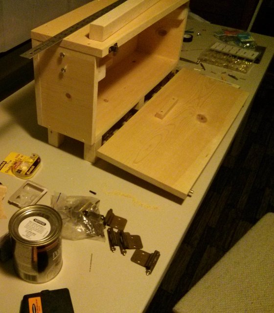
Before I could even design and print the Planetary Mass, I had to build a frame so that I could balance and test the unit indoors, sort of like a giant bow with a bowstring (the taut tether) or a sailboat mast and rigging, and the mast is primarily stabilized by a steel cable (wire rope). Below is a photo of my first test on the tether, the white string shows the desired angle of 38.6 degrees, but as you can see, the craft sits lower due to the catenary, and these offset angles are quite large due to the weight of the craft, around 8.28 lbs (3.76 kg) which is heavier than I anticipated. I used a 500-watt halogen lamp to test the solar panel and CdS LDRs, and I connected 5v USB test power to the external stainless steel terminals so that I could test it without the lamp or solar power for long periods.
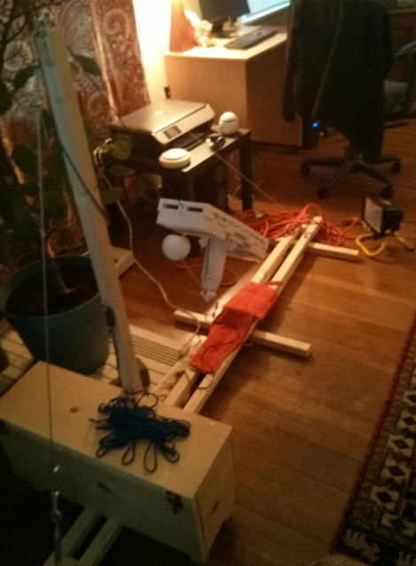
It also acts as a demonstration device that I can bring to conferences/conventions. I decided to build it out of wood to mimic the arboreal, tree-like nature of the real trees and contrast it with the high-tech plastic and metal of the unit. I also built an "Ark" which serves as the carry case and storage box for the unit, but it is also an integral part of the Test Frame, helping to stabilize and weigh it down. I enjoyed watching the 1943 documentary Uncrating and Assembly of the P-47 Thunderbolt Airplane which showed how the wooden crate was an integral "machine" that made the assembly of the plane possible with only manpower, simple tools, and the truck that delivered the crate. If you design a simple wooden box properly, it can have multiple benefits.
I have also been fascinated with my local Screamin' Eagle wooden roller coaster since I was 6 years old in 1976, when it was the largest and fastest roller coaster in the world. I still ride this thing today, along with their newer coaster The Boss, and am still amazed at the complex painted-white wooden lattice and simple bolts that hold the curvy tracks in place and withstands the forces.
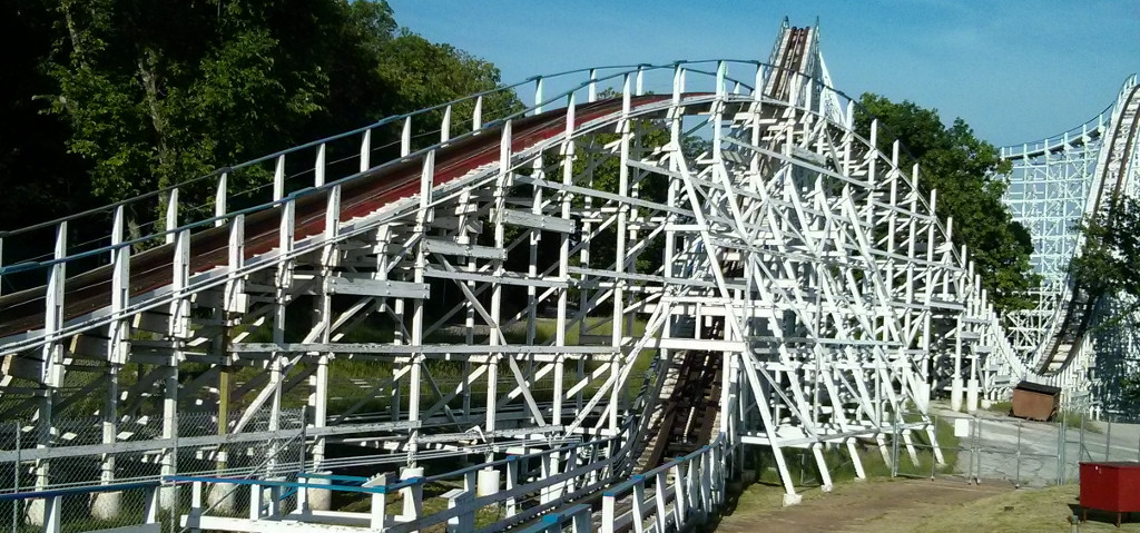
Wood is an amazing material, and scientists have even figured out how to make it stronger than steel↗.
I called it the Ark, since it is a wooden vessel, and when I was young, around that same time in the 1970's, I used to watch a television series called "Ark II" where scientists travel around a desert-like post-apocalyptic future world in a futuristic, white van, known as the Ark II, inspired by the story of Noah's Ark, a water vessel (and I've already made comparisons to how the craft mimics a water vessel). The box also brings to mind the Ark of the Covenant and reminds me of the Ark found in Tutankhamen's tomb. Curiously, the Ancient Egyptians also revered the Sun, and of course, TrillSat is solar-powered. I've had a fascination with boxes with secrets, treasure hunt games, and the mysterious VendingMachine, and this is just one more example.
Ark Mode and Frame Mode
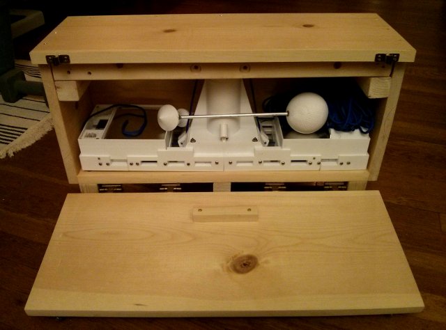
The Ark contains posts inside that can be connected to the main box to operate as a tiny stand (Ark Mode), allowing me to test the drive motors and tilt the craft to allow solar charging (or via that 500 watt light), but it won't provide enough room to test the Capstan locomotion (which is bypassed in this mode), and I don't have much room to tilt it to match that 38.6 degrees. This mode is mainly a compromise when I need to transport it but can't bring along the full frame, which is long and unwieldy.
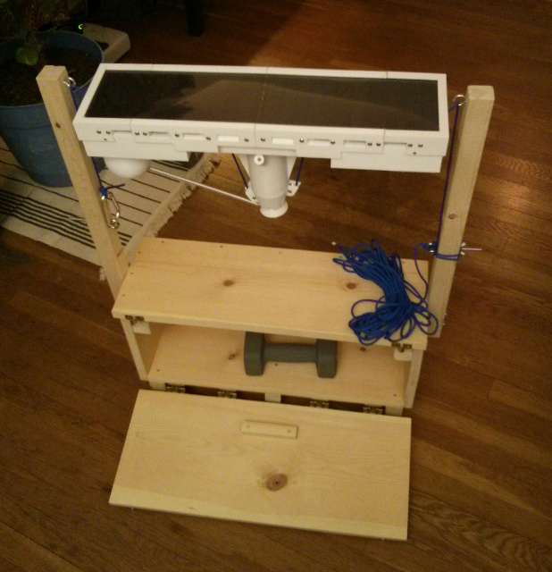
When combined with the full frame (Frame Mode), the posts stabilize the frame and allow the craft to fully operate. I used pine, which is light and cheap, but not hard nor strong, so I had to be careful to glue and reinforce it where needed. It is rather thick, but I do add some weight to keep it from tipping over easily. Pine does have complex swirly grain patterns, and the knots remind me of eddies in Jupiter's atmosphere.
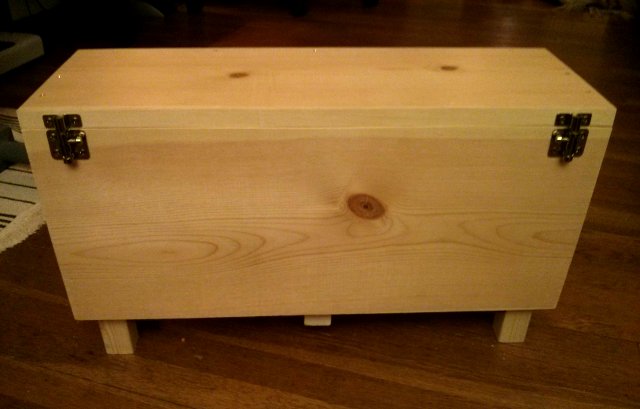
The top of the Ark has two knots in BinaryOpposition, loosely symbolic of the dualistic cherubim on the top of the Biblical Ark, but the sides only have one knot. I used butt-joint construction for simplicity but also added brass screws to aid me in clamping the glue, and used brass hinges from an old cabinet that I removed from my kitchen years ago. I didn't cover the screws as I like to see the wood/brass combination. I made sure that no fasteners were visible from the front and from the inside when the craft is in place, as I wanted to contrast the pure wood with the synthetic materials of the craft.
I added two inexpensive brass-colored window bolts to act as door latches, orienting them at the ends so they can be easily operated by a single action with opposing thumbs. If one latch manages to wiggle loose, there is another latch for redundancy. The bolt latch handles face inwards, again, like stylistic, facing cherubim. The latches also act like feet when the door is fully open.
The door opens from the side, not the top, which allows the craft to slide under mounts on the back wall and the door to hold it firmly in place when the door is closed. It also helps to brace the vertical mast and provides a nice view for demonstration purposes, but it blocks the door from opening in frame mode to access the bolts, which requires a special sequence of assembly. There is enough room for the Planetary Assembly and a coiled up Zepp antenna.
If the Ark is inadvertently turned upside-down, TrillSat should stay firmly in place and the door should remain bolted shut. The side door reveals the upright shape of the craft when the door is opened, and the door looks like a ramp to a plateau which allows me to create mysterious visuals when the LED spotlight is phasing in Demo Mode. Another television show that I used to watch from the same era in the 1970's was Land of the Lost, and I loved the contrast of the geometric "Pylons" that were juxtaposed in the wild, prehistoric forest, containing a darkened space with glowing crystals.
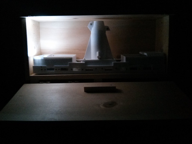
The left CdS LDR can detect when the door opens from the inrush of light and start its light display. I didn't put a handle on the top of the Ark, as I thought it could act as a table or piece of furniture when not in use. It provides a precarious display platform for the craft, but can easily tip over if bumped.
I didn't create strong legs, incorporating them into the frame, but simply screwed/glued posts on the bottom, the reason being that I needed as much interior space as possible, with the least amount of weight, so I could carry the thing around under one arm. I also inset the legs to drill the screw hole and also hide the fact that they are just glued-on posts. So I can't sit on it and use it as a bench, unfortunately.
I decided to use a halyard knot to secure the paracord to a cheap carabiner at the lower end, and at the high end, after going through a strong screw eye and wrapping around the rope hitch, I used a cleat hitch halyard knot to secure the bulk of the rope to the hitch. The rope hitch only has a 55 lb rating, so I wrapped the rope around the mast to increase the friction to take some stress off of it. Figuring out how to tie the cord quickly and securely increased my appreciation for knots, something I need to study in the future. Again, I don't live in a nautical or sea-faring port city, so my knowledge of rigging is very limited.
The frame folds up to save space, and is 6 1/2 feet (around 2 meters) in length, which fits flat into a small truck bed for transport and isn't too long to carry around for demonstration.
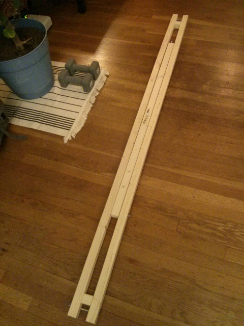
The height is just over 4 feet. It turns out that 4 feet high by 5 feet long creates an right-triangle angle of 38.66 degrees, almost my exact latitude, so I built the frame around those dimensions and used a 1/8" (3.2 mm) galvanized steel cable (wire rope) guy wire for reinforcement. Adding the guy wire takes some stress off of the weak pine central mast, made it more portable, and removed the need for strong braces, at the expense of a little bit of horizontal length. The frame, when assembled, will also sit atop a long table without hitting the ceiling.
When the frame is in use, the Ark door must be closed, but the Ark is filled with a weight to keep the unit from tipping over. The brace at the bottom lifts the frame, adding additional weight, and the mast is loosely bolted to the back to keep it from tipping sideways. The Ark itself, doesn't experience many stresses in this arrangement. The braces that hold the posts for storage inside are unbolted and help to distribute the pressure in both modes, since the pine box is rather fragile.
I decided to add a cheap, aluminum turnbuckle, a device that allows me to easily tension the wire rope with my hand so that I can remove it and eliminate any slack. I also added a small "shackle" with a clevis and pin, so that I could remove the guy wire without having to adjust the turnbuckle each time.
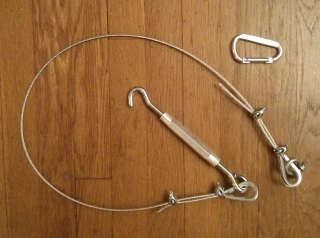
Most of the parts are rated at least 150 lbs (around 68 kg), some were rated several hundred lbs. I don't expect to get near these values, but the reason I used such thick steel cable (wire rope) instead of using the same nylon paracord to support the mast is because the thicker wire rope doesn't stretch much under the forces I am using causing the mast to pull away from the Ark. I also keep the nuts that mount to the mast slightly loose just in case the cable/wood stretches and puts stress on the weak pine of the Ark. They really only need to provide lateral stability, not along the length of the frame. Note that the bottom of the Test Frame uses twice as much wood as the mast--this helps with stability, and the bottom is like a bow, it has to absorb more tensile force than the mast (which is stabilized by opposing forces though a strong metal screw-eye and converted to compressive forces.
It was difficult to cut/measure/clamp wood in such precise ways with my simple tools, and I had to be careful with the order of construction. I used my family's old radial arm saw to cut and rip the pine pieces outside, on a very cold winter day, when I had to move quickly to prevent my hands from freezing. But the next day, I realized that my measurements were off and decided to re-cut them indoors with my cordless jigsaw using a scroll saw blade to keep the pine from splitting, but it was slow going.
Straight cuts are difficult to make, even when I created a makeshift guide, since the jigsaw was not precise, nor fast like the radial arm saw, and the blade tended to bend, but the rough aspects added some character to the box which nicely contrasted with the precision of the 3D-printed plastic. When you build a box, right-angles are a must, so I had to re-cut until they were acceptable and almost ran out of space.
I also had trouble drilling straight holes without a drill press, so in many cases I just butted the wood together and drilled a single hole to ensure they lined up, but I made errors in the angles. So some of the holes are askew, yet the frame mechanism fits together perfectly. It actually had the benefit of allowing me to detect proper orientation during assembly, as the askew holes could only match up in certain ways.
I didn't stain the pine, but will eventually coat it in oil-based polyurethane, so the pine and the polyurethane will darken over time, adding a nice aesthetic (which I know from experience from my bathroom/vessel sink project). I wanted it to look natural and the grain to stand out. I arranged the knots in the wood so they didn't interfere with the joints or screw holes, but the pine was crude and warped, so I had to wrangle the warps so they fit within the other warps. Due to the warps, I even had to make one of the legs slightly longer to be level with the ground--it's crude, but inexpensive.
I'm not a woodworker like my father or grandfather and didn't intend to create a piece of furniture but just wanted a housing for my craft. But as the days went on, the smell of pine and the nature of woodworking was cathartic and reminded me of my childhood and natural materials. After clamping my parts and waiting for the glue to dry, I watched the film Blade Runner 2049 for the first time and there was this scene where the statuette of a wooden horse was appraised as being very valuable, as wood was more precious than the CyberPunk technologies of its "retro-future". Yesterday, on March 19th, 2018, as I write this section of the page, the world's last male, northern white rhino has died, the sub-species being just about poached to extinction for their horns, and a few weeks ago, one of my heroes, Roger Bannister, the first person to break the 4-minute mile, passed away.
It got me thinking, that perhaps, decades from now, this simple, inexpensive, wooden box that only took me a couple of weeks to design and build (which I completed while watching ice dancing at the Pyeongchang 2018 Winter Olympics on television) might actually be more significant and special to me than the entire TrillSat craft that took me two years to build, which will likely be obsolete by then. Somewhere, probably in my country's northwest pine forests, this tree had a life and left its memory behind.
In the Olympics, some of the athletes gave their last performance at that level, and it reminded me of when I ran my last track race at college, knowing that I would never compete at that level again, and perhaps never run that fast again. When I finished the Ark, I realized that my first TrillSat project was coming to an end. I will never build another TRILLSAT-1.
Electronics
3D Dead-Bug Soldering
When I first began building Circuit Boards A and B, I used traditional though-hole wiring, which turned out to be a big mistake as it hides the circuit on the bottom of the board, which is inaccessible when the board is mounted, and there is not enough room to add the many high-current wires without raising the board out of its mounting box. It also makes visualizing and repairing the circuit extremely difficult, as you have to constantly flip the board around to see the wires and heat-and-yank wires out of the holes (which tend to clog with solder), a meticulous and laborious process. In Circuit board A, I caught this problem early and so a few things are through-hole, but I switched to "dead-bug" style later, flipping the components upside-down, hot-gluing them to the board, exposing their leads like a dead beetle laying upside-down on its carapace (hence, the dead-bug). This allowed me to work in 3-dimensional space instead of cramming all of the wires onto a 2-dimensional plane, making better use of the space and simplifying construction. It also allowed repairs to be performed without removing the board from the mount. For Circuit Board B, I had to rebuild the entire thing, scrapping the old board and parts, using dead-bug style the second time so that I had enough space. In my first attempt, I had to modify the circuit so many times using through-hole, that it was impossible to solder and the board wouldn't fit in place. With dead-bug style, the bottom is just the ground plane, which also simplifies wiring.
Note that I didn't go the PCB/surface mount route due to cost and time concerns. It was impractical for me to use simulation and CAD to design and build perfect circuits on the first try, and it would have taken numerous iterations, and become expensive, so dead-bug prototyping is ideal for this. Now that the circuits appear to be working, they can eventually be moved to more reliable construction methods in future prototypes.
Point-to-Point Wiring and Jumpers
Similarly, I used both high and low current terminals and jumpers on all circuit boards, connecting them via point-to-point wiring, routing the wires through channels in the PETG housing. The terminals are not designed for situations of extreme moisture or vibration but allow me to remove various pieces without having to de-solder everything.
Tools and Materials
My Electronics Lab
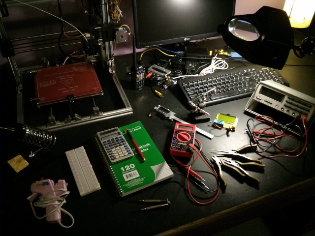
I didn't have much money, so I had to rely on what was available to me. The best cost-saver, however, is always human imagination and logic--I spent many months thinking and doing freehand sketches in notebooks with a mechanical pencil, optimizing the design.
- Test Equipment
- Micronta 22-175 True RMS Multimeter
- CEN-TECH 7 Function Digital Multimeter
- Generic AVR-based Transistor tester (I mainly use it for testing capacitors and resistors, though)
- NooElec NESDR Mini 2 RTL2832U (for SDR spectrum analyzer)
- Small breadboard from a local electronics store
- Tools
- Raspberry Pi 3 running Arch Linux ARM 32-bit (it has just enough speed and memory to allow
me to do all 3D design, printing, and packet radio testing, although I perform the CPU-intensive rendering, slicing and software-defined radio on a more powerful computer in another room) - Folger Technologies Prusa i3 2020 (a RepRap 3D printer, built from kit)
- Baofeng UV-5RA Radio (I use a second Baofeng radio with my older PacketRadio interface for testing communication to TrillSat)
- General brand digital fractional caliper
- Radio Shack 30-watt soldering iron
- Microcenter soldering iron stand
- Radio Shack helping hands (missing an alligator clip)
- Craftsman mini 3-piece box-joint pliers set
- Buffalo Tools 6-piece precision screwdriver set
- Ad tech Hi Temp mini size glue gun
- Magnifying lamp
- TI Solar Scientific Calculator
- Notebooks and pencils
- Raspberry Pi 3 running Arch Linux ARM 32-bit (it has just enough speed and memory to allow
- Hardware Tools (not shown)
- Harbor Freight aviator snips (for cutting aluminum sheet)
- Ruler, yardstick, try square, spirit level
- C clamps and pipe clamps
- Hacksaw
- Skill cordless jigsaw and sander
- Craftsman cordless drill
- Harbor Freight drill bits
- 500-watt halogen work light (for testing solar panel)
- Software Tools (under the Linux OS unless otherwise mentioned)
- OpenSCAD (3D design and rendering)
- Slic3r (3D slicing)
- pronsole.py (3D printing, from Printrun suite)
- KiCad (schematic design)
- GQRX/gnuradio (spectrum analyzer)
- 4nec2 under WINE (antenna modeling)
- Inkscape
- GIMP
- rsync
- posix_ipc
- socat
- minicom
- nodemcu-uploader
- esptool
- WiringPi
- pigpio
- hexdump (for decoding UV-5RA flash memory)
- fake-hwclock
- kissattach
- ax25d, call, beacon (ax25-tools, ax25-apps)
- Direwolf
- avrdude (with bug fixes for ATtiny 1634 flash programming)
- AVR GCC and various C and AVR Libc libraries (ATtiny 1634 C programming):
- interrupt.h
- sleep.h
- io.h
- delay.h
- sfr_defs.h
- math.h
- NodeMCU and various modules (ESP8266 Lua programming):
- ADC
- file
- GPIO
- net
- node
- ow (1-wire, but I will replace this later with DS18B20)
- RTC mem
- RTC time
- timer
- UART
- WiFi
- I2C (will add this later)
- Python 2 and 3 and various modules (Raspberry Pi Zero W programming):
- serial
- sys
- os
- time
- posix_ipc
- multiprocessing
- threading
- pigpio
- mmap
- struct
- subprocess
- binascii
- math
- string
- saxutils
- argparse
- termios
- select
- Xabber (Dev. 1.0.74, using Android AOSP)
- Opus codec (for optional net recorder based on my earlier BashTalkRadio project)
- Motion (for optional camera)
- My ScratchedInSpace webpage generator
Helpful Reference Documentation
I had to refer to a lot of datasheets, manuals, books, and protocol specifications. But I also came across a lot of nice articles written by various individuals which helped clarify certain technical concepts.
(links may be out of date)
- ATtiny 1634 datasheet↗
- L6234 datasheet↗ and app note↗
- Adafruit Huzzah ESP8266 breakout documentation↗
- ESP8266 datasheet
- Adafruit LIS3DH breakout documentation↗
- LIS3DH datasheet↗ and app note↗
- DS18B20 datasheet↗
- US5881LUA datasheet↗
- MT3608 datasheet↗
- LM2587-ADJ datasheet↗
- LM339 datasheet↗
- IRLB8721PBF datasheet↗
- NDP6020P datasheet↗
- FQP27P06 datasheet↗
- Panasonic NCR18650B datasheet
- Cmedia CM-119 datasheet
- NodeMCU module documentation↗
- UV-5R Manual
- Lior Elazary's Hacking the Baofeng UV5R↗
- Thorsten von Eicken's Serial Bridge↗
- Thomas Karpiniec's AX.25 Client and Server Programming
- Linus Akesson's The TTY demystified↗
- Dean Camera's Newbie's Guide to AVR Timers
- Larry Kenney's Introduction to Packet Radio↗
- Grog's Animated Knots↗
- Modular Circuits H-Bridge Secrets articles↗
- Battery University Lithium-ion articles
- Analysis of Solar Panel Efficiency Through Computation and Simulation by Hongyu Go and Mehrube Mehrubeoglu
- The DBJ-2: A Portable VHF-UHF Roll-Up J-pole Antenna for Public Service by Edison Fong, March 2017, QST Magazine
- elinux GPIO articles↗
- OpenSCAD User Manual↗
- Slic3r Manual↗
- APRS Protocol↗ and the later addendum and updates
- XMPP Core Protocol↗
- Pigpio Python documentation↗
- Sparkfun I2C Tutorial↗
- CHIRP Project↗
- Arch Linux Wiki↗
- Linux Amateur Radio AX.25 HOWTO
- The Linux AX.25 man pages
- The Art of Unix Programming by Eric Raymond
- The Waite Group's New C Primer Plus by Mitchell Waite and Stephen Prata
- Programming in Lua by Roberto Ierusalimschy
- Baofeng UV-5R schematic
- Dire Wolf 1.4 User Guide
- Wolfram Alpha and Wikipedia
- The ARRL Ham Radio License Manuals
- The ARRL Handbook
- The ARRL Antenna Book for Radio Communications
- MorseDecoded
- PacketRadio
Suppliers
- Digikey
- Mouser
- Adafruit
- Radio Shack (before it closed its retail stores)
- Gateway Electronics (local)
- Local dollar stores
- Microcenter
- Menards
- Home Depot
- Harbor Freight Tools
- Ebay
- Amazon
Bill of Materials
Parts cost was approximately 390 US dollars, not including the parts I already had or the cost of the smartphone that I already had.
Craft
| Name | Reference Desginator or Category | Cost |
| Sunpower Solar Cells (Extracted from X-Dragon 14W Solar Charger) | PV1, PV2 | $31.99 |
| Baofeng UV-5RA Ham Radio with headset | U4 | $26.29 |
| SYBA SD-CM-UAUD USB Stereo Sound Adapter (CM119 chip) | U3 | $4.99 |
| Raspberry Pi Zero W | U1 | $9.99 |
| Raspberry Pi Camera and Pi Zero cable | U2 | Not purchased |
| Adafruit Huzzah ESP8266 Breakout (Espressif) | U5 | $9.99 |
| Attiny 1634-SU 8-bit Microcontroller (Atmel) | U11, U19 | $3.08 |
| Adafruit LIS3DH 3-axis Accelerometer (STMicroelectronics) | U14 | $4.95 |
| L6234 3-Phase Motor Driver (STMicroelectronics) | U10 | $6.47 |
| LM339 Quad Comparator | U12 | $1.00 |
| MT3608 DC-DC Step Up Board | U16 | $8.98 |
| LM2587S Adjustable Step Up Voltage Regulator board | U17 | $9.20 |
| USB Lithium-ion Charger (Extracted from ikits USB Powerbank) | U21 | Already included |
| USB Solar Charge Controller (Extracted from X-Dragon 14W Solar Charger) | U20 | Already included |
| Qi Wireless Charger PCB Circuit Board With Coil | U18 | $4.98 |
| Maxim DS18B20+ Programmable Resolution 1-Wire Digital Thermometer | U6, U9, U13, U15 | $11.12 |
| Melexis US5881LUA Unipolar Hall Switch | U7, U8 | $2.18 |
| Panasonic NCR18650B Lithium-ion cell (Extracted from 2 iKits 10200mAh USB Power Banks) | BT1, BT2, BT3, BT4, BT5, BT6 | $21.98 |
| 13 ohms | R11 | $0.20 |
| 100 ohm 1/4W 1% Metal Film | R2, R29, R35 | $0.10 |
| 130 ohm 1 watt | R20, R26 | $0.40 |
| 147 ohm 1/4W 1% Metal Film | R21, R22, R23, R24 | $0.80 |
| 402 ohm 1/4W 1% Metal Film | R36 | $0.20 |
| 1k 1/4W 1% Metal Film | R8, R9, R10, R12, R13, R19, R25, R28, R31, R37, R39, R40, R41, R42, R43, R44, R45, R46, R53 | $1.37 |
| 3570 ohm 1/4W 1% Metal Film | R3 | $0.25 |
| 4.7k 1/4W 1% Metal Film | R16 | $0.12 |
| 10k 1/4W 1% Metal Film | R1, R4, R7, R14, R15, R17, R18, R30, R32, R33, R34, R52, R55, R56 | $0.45 |
| 20K 1/4W 1% Metal Film | R47, R48, R49, R50, R51, R54 | $0.19 |
| 38.3K 1/4W 1% Metal Film | R5, R6 | $0.60 |
| CdS Photo Resistor (Adafruit 161) | R27, R38 | $1.90 |
| Thermistor (type unknown, extracted from ikits USB Powerbank) | TH1, TH2 | Already included |
| 4.7uF Tantalum | C1, C2 | $1.00 |
| 2200uF 35v Electrolytic | C12 | $1.80 |
| 10nF Ceramic | C14 | $0.25 |
| 100 uF, 50v Electrolytic | C3, C8, C11 | $0.45 |
| .1 uF 50v Ceramic | C4, C9, C10, C13 | $0.25 |
| 1 uF Electrolytic | C5 | $0.25 |
| .01 uF 100v Ceramic | C6 | $0.25 |
| .22 uF 25v Ceramic | C7 | $0.25 |
| Kobitone 254-PB305-ROX Piezo Element 30 × 9.5mm 2.5 Khz | X1 | $1.44 |
| 5 white COB LEDs (100 Lumen, extracted from a TOMOL Super Bright COB LED Mini Flashlight) | D1 | $1.27 |
| 1N4148 Silicon Diode | D7, D8, D10, D11, D18 | $0.50 |
| 1N4002 Silicon Diode | D19 | Already had |
| Zener Diode 4.7v 500 mW | D13, D14, D15, D16 | $0.52 |
| Zener Diode 6.2v 400 mW | D2, D17 | $0.26 |
| Schottky Diode 1A | D3, D4, D5, D6 | $3.00 |
| Schottky Diode 7.5A | D9, D12 | $2.92 |
| 2N3904 NPN Transistor | Q1, Q2, Q6, Q7, Q14, Q15, Q16, Q17, Q18, Q19, Q20, Q21 | $2.28 |
| 2N2222 NPN Transistor | Q5, Q8, Q13 | $0.60 |
| IRLB8721PBF N-Channel MOSFET | Q10, Q12, Q27 | $2.30 |
| FQP27P06 P-Channel MOSFET | Q4, Q9, Q11 | $3.99 |
| NDP6020P P-Channel MOSFET | Q3, Q22, Q23, Q24, Q25, Q26 | $11.40 |
| HK19F-DC_5V-SHG DPDT Relay 2A 5V 200mW coil | K1 | $2.50 |
| RT424F05 DPDT Latching Bistable Relay 8A 5V | K2 | $6.79 |
| Momentary SPST PCB Switch 7.6 × 7.8 × 6mm | SW1 | $0.50 |
| 10A PCB Axial Lead Fuse | F1 | $0.75 |
| 5A PCB Axial Lead Fuse | F2 | $0.75 |
| Dual 3.5mm TRS (Extracted from two 3.5mm stereo plugs) | J1 | $1.50 |
| Baofeng 2-pin_connector (extracted from Baofeng UV-5RA Headset Mic) | J2 | Included in list |
| Screw Terminal 2-position .2 pitch | J3, J4, J5, J9, J6 (3), J7 (3) | $5.00 |
| Dual Row Headers 0.1" Spacing 80 | JP1, JP2, JP3, JP4, JP5, JP6, JP7, JP8 | $8.49 |
| Jumper Wires Female to Female 2×40pcs 2.54mm 0.1" | Wire | $4.65 |
| Alligator Cliplead Jumper Wires 2.5" Set of 5 | Wire | $3.95 |
| 18 gauge stranded wire (15') | Wire | $3.00 |
| 24 gauge solid wire (cut from round 4-conductor telephone cable) | Wire | $0.00 |
| 50 ohm coax pigtail | Wire | Not purchased |
| Prototype PCB Board | PCB1 | $1.50 |
| Prototype PCB Board 2 1/2" × 3 1/4" | PCB2 | $1.29 |
| DC Motor & Gearbox (Extracted from Black & Decker AS6NG Cordless Screwdriver) | M1 | $8.50 |
| BLDC motor with 3 Hall-effect sensors (Extracted from an old Lite-on DVD drive) | M2 | Already included |
| 300-ohm Flat Twin-Lead Antenna Wire (for Zepp Antenna) | AE1 | Already had |
| Small round rare-earth magnet (extracted from Baofeng UV-5RA Headset Mic) | Misc | Already included |
| Small round rare-earth magnet (extracted from earbuds) | Misc | Already had |
| Female SMA bulkhead adapter | Misc | Not purchased |
| Female SMA PCB Jack | Misc | $1.58 |
| Clear Acrylic Sheet 18" × 24" x .100", High-gloss, UV-resistant | Hardware | $12.98 |
| Thin Clear PET (Extracted from Blueberry produce container) | Misc | Already had |
| Aluminum Angle Bar 1/16" × 1/2" × 36" 6063-T5 Alloy | Hardware | $2.49 |
| Aluminum Round Solid 1/4" × 4' 6063-T5 Alloy | Hardware | $4.13 |
| Aluminum Sheet .025 × 12" × 24" 3105-H24 Alloy | Hardware | $14.99 |
| 624VV 4 × 13 × 6mm 1.7mm Sealed Vgroove Ball Bearing | Hardware | $6.10 |
| Brass Plated Wood Screw Assortment | Hardware | $4.99 |
| #6-32 × 1/2" Phillips Pan Head Stainless Steel Machine Screws | Hardware | $1.59 |
| #6-32 × 1" Phillips Pan Head Stainless Steel Machine Screws | Hardware | $1.59 |
| #6-32 × 2" Phillips Pan Head Stainless Steel Machine Screws | Hardware | $1.59 |
| #6 Stainless Steel Split Lock Washers | Hardware | $1.59 |
| #6-32 Stainless Steel Hex Nuts | Hardware | $3.18 |
| #8-32 × 5/8" Phillips Flat Head Stainless Steel Machine Screws | Hardware | $1.59 |
| #8-32 × 1 1/4" Phillips Flat Head Stainless Steel Machine Screws | Hardware | $1.59 |
| #8-32 Stainless Steel Hex Nuts | Hardware | $3.18 |
| four #6 × 1 1/2" Philips Flat Head Solid Brass Wood Screws | Hardware | $0.82 |
| Various small screws for Circuit Board Mounting | Misc | $2.00 |
| Various wire ring terminals | Misc | $0.50 |
| Various hardware for staking tether into ground | Hardware | Not purchased |
| Daisy Premium Grade BBs (.177 caliber, zinc-plated steel, box of 1500) | Misc | Already had |
| Slingshot Shot | Misc | Already had |
| Google Nexus 4 Smartphone (running Android AOSP and Xabber Dev 1.0.74) | Misc | Already had |
| Inland 1.7mm PETG Filament White 1kg (2 spools) | Viscous | $37.98 |
| Ad-Tech Pro Strength Mini Size Hi Temp Gluesticks | Viscous | $4.97 |
| White Lightning Clear Silicone Ultra Gutter & Flashing Sealant | Viscous | $5.29 |
| Gorilla Clear Epoxy | Viscous | Already had |
| JB Weld Epoxy | Viscous | Already had |
| 3M 9703 2" × 6" Conductive Z-Axis Tape (about $4.95) | Tape | Already had |
| Copper Foil Tape 5mm x 50' | Tape | $3.95 |
| Kapton Tape (about $4.95 at store) | Tape | Already had |
Test Frame
| Name | Category | Cost |
| Four 2×2x8 Furring Strip SPF Boards 1.5" actual thickness | Lumber | $7.32 |
| 4 1/2 feet 1/8 " galvanized wire rope | Hardware | $1.44 |
| four 3/32 in - 1/8 in zinc-plated wire rope clips | Hardware | $1.94 |
| two 1/8" zinc-plated Wire Rope Thimbles | Hardware | $0.98 |
| Lag Screw Eye 5/16" × 4" 175 lb Safe Working Load | Hardware | $0.87 |
| 3/16" Galvanized Anchor Shackle, 665 lb Working Load Limit | Hardware | $1.55 |
| Turnbuckle (aluminum) 3/8" × 10 1/2", 215 lb Safe Working Load | Hardware | $1.96 |
| 5/32" × 50' Blue Nylon Paracord, 110 lb Working Load Limit, 550 lb Breaking Strength | Rope | $3.97 |
| Rope Cleat 4 1/2", 55 lbs. Maximum Load | Hardware | $1.39 |
| Aluminum Spring Link (carabiner), 150 lb Working Load | Hardware | $0.98 |
| Several #8 Flat Washers - used two to allow use of larger washers for rope cleat | Hardware | Already had |
| 2 old round head, slotted machine screws and nuts (to secure rope cleat to mast) | Hardware | Already had |
Ark
| Name | Category | Cost |
| two 1" × 12" × 6' Common Board (Ponderosa Pine), .75" actual thickness | Lumber | $13.84 |
| five boxes of #6 × 1 1/4" Philips Flat Head Solid Brass Wood Screw | Hardware | $4.10 |
| four Amerock Self-Closing Burnished Brass Hinges (re-used from my old kitchen cabinets) | Hardware | Already had |
| two 2" Brass-Toned Steel Window Bolts (for door latches) | Hardware | $2.74 |
| eight #8 × 3/4" Philips Flat Head Brass Plated Wood Screw (for door hinge) | Hardware | Already included |
| eight #8 × 1" Philips Flat Head Brass Plated Wood Screws (for door hinge) | Hardware | Already included |
Ark and Test Frame
| Name | Category | Cost |
| Twelve 1/4" – 20 × 5" Zinc Plated Carriage Bolts | Hardware | $1.89 |
| 1/4" Zinc Plated Flat Washers | Hardware | $3.49 |
| 1/4"-20 Zinc Plated Wing Nuts | Hardware | $3.49 |
| Minwax Fast Drying Polyurethane, 1 Qt. Clear Gloss, Oil Based (re-used from my old bathroom sink project, approx. $12 today) | Viscous | Already had |
| Titebond Original Wood Glue, 8oz. (re-used from my old bathroom sink project, approx. $3 today) | Viscous | Already had |
| 2 3/4" 14 TPI Jig Saw Scroll Blades (for my Skil Cordless Jig Saw) | Tools - consumable | $1.99 |
| 180 Grit Hook & Loop Sandpaper (for my Skil Cordless Sander) | Tools - consumable | $3.29 |
Operation
Program Description
(Please note that this page was originally generated in HTML. If you are reading this as a text README file inside the source tarball, it will not contain any hyperlinks and the program lines may be truncated.)
Warning: This software is HIGHLY experimental! I created it for myself to test my TRILLSAT-1 robotic prototype; it is full of bugs and NOT recommended for actual use without significant changes and improvements. You will most likely aggravate yourself and waste a lot of time, energy and resources trying to replicate this project. In fact, even though I created the TrillSat project, I can barely even get the thing working myself since there are so many fragile, interacting components. But for me, it is a fun challenge--for you, it could be a nightmare.
Also note that I am not an engineer and have created this system for my own use and self-education only, with the hope that providing information about the project will be useful to others in some way. It might not be suitable for you, and I am not responsible for the correctness of the information and do not warrant it in any way. It requires skills in Linux, programming, 3D printers, electronics, and robotics to understand many of the concepts involved. This project also contains references to Amateur Radio technologies that may require licenses in your country, but the robotic platform can be adapted to use license-free consumer radio technologies with varying results.
I am hoping however, that this particular arrangement of ideas, systems, and modules might inspire someone, educate, or solve a problem somewhere.
The home page for this project is http://greatfractal.com/TrillSat.html, which provides in-depth technical information and philosophical insights that I learned along the way.
If you're reading this in the text README file and not the website, here's a very brief summary of this project:
The TrillSat project was created by me, Lee Djavaherian, in St. Louis, Missouri in 2016 and most of the building and programming of the TRILLSAT-1 prototype was completed by 2018. It is an experimental, solar-powered, robotic radio relay with a 2m/AX.25 to WiFi/XMPP gateway and multi-user PBBS with in-session APRS beaconing over a single VFO. It has a weatherproof, temperature-controlled, low-cost design and uses a capstan hoist to climb a single, nylon tether to achieve high elevation for line-of-sight VHF, using the same drive motor for pendular tilt of a solar tracker. This kinematic constraint and catenary of the tether restricts the angle to an arcing, spiral axis for near dual-axis efficiency which is aligned using an accelerometer, Hall-effect, and LDR sensors. To counter the tangential sway, the craft includes a passive ball damper, slow PWM startup routines, experimental sway-cancellation, gyroscopic reaction wheel and inertial stabilizer. An inductive Qi coil allows smartphone charging and a dock for a future LoRa "space pod". It includes mechanical energy re-capturing for motor assist.
It also includes an experimental haptic Morse Code system which depends on a separate module that I created called SIMTHEO Decoder that isn't part of the TrillSat software package.
There are several source files that comprise this project:
- The electrical schematic (drawn in KiCad)
- The mechanical 3D-printed part generator (designed in OpenSCAD)
- The C source code (for the 2 ATtiny's Sawyer and Huckleberry)
- The Lua source code for the ESP8266 running NodeMCU
- The BASH and Python source code for the Raspberry Pi Zero W
Many of these source files also have numerous dependencies such as Arch Linux OS and a lot of GNU software, NodeMCU modules, C and OpenSCAD libraries, and Python modules, which are detailed under each of the sections below.
Here are some of the main tools used at the OS level:
- posix_ipc (for PBBS message queues)
- socat (for testing AX.25 over pseudoterminals in simulation)
- minicom (for initial UART testing and headless serial consoles and to access the ESP8266 NodeMCU console)
- nodemcu-uploader (uploading my NodeMCU source)
- esptool (for upgrading the ESP8266 with new versions of NodeMCU)
- WiringPi (so BASH can set/check GPIO status)
- pigpio (allows I2C, virtual UART, Python GPIO control)
- hexdump (for decoding UV-5RA flash memory)
- fake-hwclock (for preserving time, somewhat, across reboots)
- kissattach (for testing AX.25 over pseudoterminals in simulation)
- ax25d, call, beacon (ax25-tools, ax25-apps) - actual AX.25 communication
- Direwolf (software modem)
- avr-gcc (C compilation of the ATtinys)
- AVRDUDE (with bug fixes for ATtiny 1634 flash programming)
- rsync (to allow efficient publishing of source code changes over ssh from another computer)
- i2ctransfer and i2cdetect (for communicating with I2C)
config.txt
Once Arch Linux ARM was installed on the Pi Zero W and setup via headless ssh remote access, changes were made to the /boot/config.txt file.
Bluetooth was disabled to use the primary PL011 UART at /dev/ttyAMA0, 1-Wire support was enabled for the DS18B20+ sensors, I2C support was enabled for the ESP8266 and the two ATtinys. I2C was also slowed to 50 Khz to work around the clock-stretching bug, and PWM was enabled for the piezo element. The GPU memory was kept rather low to conserve memory since the unit is headless (but making it too low can have detrimental effects in some cases). Turbo mode was enabled full-time to allow radio programming and Dire Wolf decoding to be more reliable. It is as follows:
force_turbo=1
dtoverlay=pi3-disable-bt
dtoverlay=w1-gpio

# slowed down hardware i2c to 50khz to work around rpi clock stretching bug
dtparam=i2c_arm=on
dtparam=i2c_arm_baudrate=50000

# dtoverlay=pwm,pin=18

# being stereo, this seems to interfere with gpio 19 used by Huckleberry RST line
# this should be changed to mono later, commented out for now:
# dtoverlay=pwm-2chan,pin=18,func=2

gpu_mem=64
initramfs initramfs-linux.img followkernel
cmdline.txt
The /boot/cmdline.txt file was also configured as follows for my particular hardware:
root=/dev/mmcblk0p2 rw rootwait console=tty1 selinux=0 plymouth.enable=0 smsc95xx.turbo_mode=N dwc_otg.lpm_enable=0 elevator=noop fsck.mode=force fsck.repair=yes
trillsat.c
The trillsat.c source file is actually a combined source file for the two ATtiny 1634 CPU's Sawyer and Huckleberry. This allowed me to work on both of them simultaneously for efficiency, as they shared much of the same code between them. It allowed me to visualize them both at once. However, there are substantial differences in their operation (their default pin settings are different: they are connected to different circuits with different functions, and they are wired to different reset lines.)
So I used the C preprocessor #ifdef conditionals to only compile the code if SAWYER or HUCKLEBERRY is defined as 1, and this line is modified by the BASH scripts called trillsat_burnsaw.sh or trillsat_burnhuck.sh before the code is compiled and burned to the relevant chip. So code outside of #ifdef SAWYER or #ifdef HUCKLEBERRY sections is shared code, but the rest is only compiled for that particular chip using the intermediary files sawyer.c and huckleberry.c.
The trillsat.c code is the lowest-level operating code on TrillSat and forms the basis of the solar, robotic platform that can carry the higher-level CPU's and radios. The craft can operate on only trillsat.c (and even partially operate with just sawyer.c or huckleberry.c working), but trillsat.c is designed to allow the Raspberry Pi Zero W and ESP8266 to send Sawyer, Huckleberry, and the LIS3DH accelerometer commands over their I2C lines. Due to the Pi's hardware clock-stretching bug, a job-queuing mechanism was created to allow trillsat.c to process commands and report back later, rather than tying up the I2C line, which also has other benefits.
This code communicates with several sensors (CdS LDRs, Hall-effect sensors, voltage monitoring via ADCs, interrupt line of LIS3DH, and controls several switching circuits (BJTs, MOSFETs, relays, motors, LED).
The trillsat.c source relies on the AVR GCC compiler and various C and AVR Libc libraries such as:
- SIMTHEO.h (for the haptic Morse decoding)
- eeprom.h
- interrupt.h
- sleep.h
- io.h
- delay.h
- sfr_defs.h
- math.h
This file is expected to exist in the directory /trillsat on the root of the Raspberry Pi Zero W.
trillsat_burnsaw.sh
This script is used to compile and burn the trillsat.c Sawyer code onto the Sawyer ATtiny 1634 microcontroller while in-circuit, using the Raspberry Pi Zero W's GPIO port. I typically create a BASH alias called burnsaw to run this script after I make changes to the trillsat.c source code. I keep it in the /trillsat directory.
The script checks GPIO 5 to ensure that Huckleberry does not have the LED spotlight turned off and the Hall-effect sensor on that line is not sinking, both of which block programming on Sawyer. It instructs Huckleberry to turn on the LED spotlight, but exits if the Hall-effect sensor is sinking. This line is shared with several other functions since I ran out of IO pins, and the sinking issue can be remedied by turning the capstan a few degrees away from the sensor.
It then compiles the script and requires that the user hit enter to write or "burn" the code to flash. This provides an escape point if the code were to error during compile, allowing me to CTRL-C to break out before burning. Code with errors should NOT be burned to the chip, or it could cause unpredictable results that could damage the device.
This script relies on several things:
- trillsat_saw_avrdude.conf (file below)
- i2ctransfer (part of i2c-tools) to send the command to Huckleberry
- i2cdetect (part of i2c-tools)
- avr-gcc
- avrdude
- WiringPi
trillsat_saw_avrdude.conf
In order to allow trillsat_burnsaw.sh to burn the correct code to either Sawyer or Huckleberry, it swaps out the SPI bit-bang programmer's reset line in AVRDUDE and then inverts it. Huckleberry's reset line is connected to GPIO 19 (inverted) and Sawyer's reset line is connected to GPIO 13 (inverted). The tilde ~ is used to invert the lines because I added two BJT transistors to the reset lines of Sawyer and Huckleberry to allow the Pi and ESP8266, which use 3.3 volt logic, to supply a full 5 volt high to the ATtiny 1634's reset pins. This was necessary since I decided to run the ATtinys at 5 volts, and the 3.3 volt high on the reset lines was too low for reliable operation (the chips sporadically reset), so the transistors stabilized this, but they inverted the reset logic (which is why I had to use the ~ to invert them back). A working avrdude.conf file (found at /etc/avrdude.conf) should be copied to /trillsat/trillsat_saw_avrdude.conf and then edited to change the following lines:
programmer
  id    = "linuxgpio";
  desc  = "Bitbang the Raspberry Pi Zero W GPIO to program the ATtiny 1634 called Sawyer";
  type  = "linuxgpio";
  reset = ~13;
  sck   = 3;
  mosi  = 2;
  miso  = 5;
It is also worth noting that there are two bugs in the latest released 6.3 version of AVRDUDE at the time of this writing that have to be fixed before it will correctly program the ATtiny 1634:
http://savannah.nongnu.org/bugs/?40144
http://savannah.nongnu.org/bugs/?47550
And AVRDUDE has to be compiled with the --enable-linuxgpio=yes option for bitbang support. In Arch Linux, I used the Arch Build System to make the corrections in the source and then recompiled. Then I also edited this conf file and the trillsat_saw_avrdude.conf file (mentioned below) to add the other bug fix to the ATtiny1634 section.
So it takes a while to get AVRDUDE working on for the ATtiny 1634 microcontrollers first...
trillsat_burnhuck.sh
This does mostly the same thing that trillsat_saw_avrdude.conf does above, except that it burns the trillsat.c source to Huckleberry instead (and it doesn't have to worry about the sinking Hall-effect sensor or itself keeping the MISO line low). But it does have to issue a command to Sawyer to turn off its haptic interrupt so it doesn't see programming signals as Morse code commands. I typically create a BASH alias called burnhuck to run this script.
This script relies on several things:
- trillsat_huck_avrdude.conf (file below)
- i2ctransfer (part of i2c-tools) to send the command to Sawyer
- i2cdetect (part of i2c-tools)
- avr-gcc
- avrdude
- WiringPi
trillsat_huck_avrdude.conf
Similar to trillsat_saw_avrdude.conf, this is the AVRDUDE conf file for Huckleberry (with its unique reset line) that also needs to be copied, renamed, and edited:
programmer
  id    = "linuxgpio";
  desc  = "Bitbang the Raspberry Pi Zero W GPIO to program the ATtiny 1634 called Huckleberry";
  type  = "linuxgpio";
  reset = ~19;
  sck   = 3;
  mosi  = 2;
  miso  = 5;
init.lua
NodeMCU on the ESP8266 runs this file at boot. I use this file to hold intial configuration variables (usernames, passwords, SSIDs, IP addresses, port) and autoconnect (in station mode) to the wifi network and then launch the main program trillsat.lua. Note that some server values are hard-coded and it expects a 24-bit network prefix (/24), the XMPP server name is always "esp"), and the XMPP bot username is "espbot".
The init.lua (and trillsat.lua below) files require several NodeMCU modules to be present:
- ADC
- file
- GPIO
- net
- node
- ow (1-wire, but I will replace this later with DS18B20)
- RTC mem
- RTC time
- timer
- UART
- WiFi
- I2C (will add this later)
Assuming NodeMCU is already installed with the correct modules, nodemcu-uploader is used to upload the files from the Raspberry Pi Zero W to the ESP8266 while in-circuit via an ssh connection.
First, "sudo systemctl stop trillsat_bot" needs to be done to shut down the bot to prevent UART interaction. In Xabber, the esp needs to be disconnected if connected. Then the "espreset" alias is run to reset the ESP and bootstrap the Pi Zero W. Then the "upload" alias should be run which does the following:
cd /trillsat;nodemcu-uploader --start_baud 9600 --baud 9600 --port /dev/ttyAMA0 upload init.lua trillsat.lua --restart
After the upload of these two files, "espreset" should be done again, and then connection via Xabber should be possible to confirm it is back up. Then "sudo systemctl start trillsat_bot" will re-activate the bot.
trillsat.lua
This is the main source code for the Huzzah ESP8266 board, which I have running NodeMCU. It contains a very basic XMPP server that I wrote to communicate with Xabber and is not fully standards compliant.
It also communicates with the Raspberry Pi Zero W over the UART and can control the GPIO pins. It is designed to auto-switch to access-point mode if it loses connection to a router.
trillsat_bot.py
This is the main program running on the Raspberry Pi Zero W, which allows UART communication with the ESP8266, virtual UART communication with the Baofeng UV-5RA radio, and I2C communication to the ATinys and the LIS3DH accelerometer. It performs the floating point math calculations needed for pitch/roll, and solar angles, and takes granular control over the UV-5RA flash programming to change frequencies on-the-fly and control the LCD display.
It also orchestrates and facilitates communication between the remote packet radio callers and the station operator, routing messages between the multi-user PBBS instances which are spawned on connection and sending them over POSIX message queues and UARTs to allow XMPP communication.
It updates the XMPP presence with the craft's status.
It resides in /trillsat and requires the following Python modules.
- serial
- sys
- os
- time
- posix_ipc
- multiprocessing
- threading
- pigpio
- mmap
- struct
- subprocess
- binascii
- math
- string
- trillsat_motordrive.py
It was written to work in both Python 2 and Python 3, but there are some issues at the time of this writing and Python 2 is currently used.
trillsat_bot.service
This is the systemd service to allow trillsat_bot.py to run at boot. This allows the ESP8266 to turn on the Pi, and then trillsat_bot will begin communicating after it boots up. I copy it to "/usr/lib/systemd/system/" and then run "sudo systemctl enable trillsat_bot" to enable and "sudo systemctl start trillsat_bot" to start. It is as follows:
[Unit]
Description=trillsat_bot

[Service]
ExecStart=/trillsat/trillsat_bot.py &> /dev/null
Restart=on-failure
RestartSec=60

[Install]
WantedBy=multi-user.target
trillsat_motordrive.py
These are the floating point math routines for the Delta-v Motor Drive System. This is a Python module containing functions that are called by both trillsat_bot.py and trillsat_motordrive_graphme.py.
It resides in /trillsat and requires the following Python modules:
- sys
- os
- math
- matplotlib
- numpy
- scipy
trillsat_motordrive_graphme.py
This is a small script that hardcodes certain parameters and calls trillsat_motordrive.py to calculate the floating point math routines for the Delta-v Motor Drive System. It is only meant to run on a separate, desktop Raspberry Pi with a monitor to allow graphing the values produced for testing and visualization.
It does the following:
- Displays a table of important mathematical values
- Graphs the angle of the motor shaft (capstan) at a particular point T
- Graphs the horizontal roll of the solar panel at a particular point T
- Graphs the tether curve in space, between the Tree and Ground (or a ground post)
- Graphs the vertical tilt of the solar panel at a particular point T (tangent)
- Graphs a graphical estimation of the torque curve (requires that the torque table be pre-generated on a previous run of this program first)
- Displays the option of generating and saving entire torque tables to files in /trillsat/torquetables/ which can later be transferred to TrillSat for testing. It pauses on local maximum and minimums for capstan to examine error points.
Files created are:
** trillsat_minutetorque (scaled to 10-bit integers for ATtiny)
** trillsat_minutetorque_for_graphing (floating point for graphing)
** trillsat_camstan_torque (converted values for OpenSCAD polygon)
It resides in /trillsat and requires the following Python modules:
- sys
- math
- trillsat_motordrive.py
trillsat_bbs.py
This program is spawned by ax25d whenever a remote caller connects to the packet station that is listening over-the-air. It may be spawned multiple times, once for each caller that connects, and it creates a unique POSIX message queue for that caller to communicate with trillsat_bot.py. It presents a BBS menu to each connected user, but also has the ability to detect calls on another port for remote text reception only (but there is a current bug that hasn't been solved yet).
It resides in /trillsat and requires the following Python modules:
- sys
- os
- time
- posix_ipc
- multiprocessing
- argparse
- termios
- select
It requires careful configuration of AX.25 config files.
This was designed to work with Python 2 and Python 3, but I currently have it working with Python 3.
trillsat_config.py
These are global python settings for the trillsat_bot.py and trillsat_bbs.py files.
trillsat_get_therm.sh
This is a BASH script that is run once a minute via CRON using the * * * * * /bin/bash /trillsat/trillsat_get_therm.sh line. It generates temp files in the /temp folder called trillsat_thermtmp and trillsat_therm which are read by trillsat_bot. It has to run at least once to create trillsat_therm before trillsat_bot will even launch (since it looks for that file). It simply reads the four 1-wire DS18B20+ temp sensors via the Linux OS on the Pi Zero W. I had to add this script since my trillsat_bot code could not read those 1-wire devices without corruption, even if I used os-level commands. I'm not sure what is causing this issue, but this is a temporary work-around (with a 1-minute delay between reads).
direwolf.conf
This /trillsat/direwolf.conf file is the config file for use by Dire Wolf software modem. It is as follows for the SYBA CM119 USB audio device:
#by using default instead of plughw, ALSA allows sharing of device and removes dead-air PTT bug
ADEVICE  default:Device

ARATE 48000
ACHANNELS 1
CHANNEL 0
MYCALL TEST01-1

#using A uses less CPU and keeps it from crashing.  Don't use /3 or + either.
MODEM 1200 1200:2200 A
TXDELAY 90
TXTAIL 10

#Inhibit input if GPIO 27 is high (I have jumpered this to GPIO 22 to allow me to control it)
TXINH GPIO 27
PTT GPIO -9

#disable these
AGWPORT 0
KISSPORT 0
ax25d.conf
This /etc/ax25/ax25d.conf file contains the callsigns and two mode settings (the normal PBBS mode and the remote text only mode, which are numbered the same as the SSID for clarity). This tells the ax25d daemon to launch trillsat_bbs.py with the correct delimiter, mode number and callsigns when an incoming packet radio call is received. It is as follows:
# /etc/ax25/ax25d.conf
# Using TEST01 in place of callsign for testing
[TEST01-1 via 1]
NOCALL   * * * * * *  L
default  * * * * * *  - root /trillsat/trillsat_bbs.py bbs --delimiter 13 --port %d --remotecallsign %U --remotecallandssid %S --mode 1
#
[TEST01-2 via 1]
NOCALL   * * * * * *  L
default  * * * * * *  - root /trillsat/trillsat_bbs.py bbs --delimiter 13 --port %d --remotecallsign %U --remotecallandssid %S --mode 2
#
trillsat_pbbs_info
This is just a text file that provides information to the remote PBBS caller whenever the "i - information about the PBBS" is selected from the menu. The Station Operator needs to edit this file before using.
axports
The /etc/ax25/axports file associates callsigns with identifiers. This allows calls to certain callsigns to go to certain numbers (1, 2, 3, etc), but these numbers are just for reference in the call command and aren't actual ports. They could even be text strings. It is as follows:
# /etc/ax25/axports
#
# The format of this file is:
#
# name callsign speed paclen window description
# add TEST01 instead of callsign for testing

1 TEST01-1       1200     255     7     This matches the primary PBBS SSID so APRS beacons show a nice return SSID and should match stationcall in trillsat_config.py
trillsat.scad
This is the OpenSCAD program that I created to generate the 3D PETG mechanical parts for TrillSat. Most of it is parametric, with a large number of variables defined in the beginning, but as it got more complex, I had to tweak a lot of measurements and about 25% of the code is riddled with hard-coded values.
At the top of the file, you can set the showpart variable to one of several numbers listed to either show the individual part (which can then be rendered and then exported to an STL file for printing). The $fn variable will increase the number of fragments for smoother shapes. I keep it low around 20 for viewing, and set it to 200 when rendering to print. However, a value of 200 is very high, and takes a lot of computing power and several minutes to render each part. The Gyrofan took too many resources on my computer, so I rendered it with lower fragments at 100.
Setting showpart values of 100 or larger have a special significance in my code, as they generate full assemblies of the entire craft:
- 100 show full assembly
- 101 show full assembly with tether (to calibrate angles)
- 102 show exploded view (without Circuit Box covers)
- 200 show animation
It is not advisable to use large $fn values when showing the full assembly or animating, since it takes a very long time to render.
trillsat_schematic.png
This is the electrical schematic for TrillSat, created in KiCAD and then plotted to PNG. Version 1.0 has a few typos in the comparator pin names for the BLDC, and the BLDC jumper has been replaced with a ZIF ribbon cable socket. There is also a missing 5 volts that should be applied on the long horizontal wire between the two photocells.
The Status Screen
XMPP Presence is used to display the craft's status, like a mini dashboard display. It currently displays the following:
Batt 1 Percentage, Batt 2 Percentage, Just Started Indicator, Roll Angle, Pitch Angle, Orbit Position, Solar Charge Mode, Charger Relay Status, Solar Charge Switch Status, Solar Power Indicator, Batt Mode (Series or Parallel), 5.1 on/off, 5.2 on/off, 7.1 on/off, 7.2 on/off, New Mail Indicator, On-the-Air Indicator, Callsigns of All Connected Users, Radio Frequency, Time of Day
Many of the indicators disappear when off to allow more space for other items, and the smartphone can be turned sideways to expand the list if it gets truncated.
Commands
ESP8266 XMPP Commands
| esp hi | Tell ESP8266 to send a response to see it is working. |
| [pres|pres2] | Set XMPP presence to "Hello" and "There" for testing purposes. |
| blink | Blink Huzzah LED for testing purposes. |
| esp light [on|off] | Turn the LED light on or off, Pi and Hall Sensor can override. Light is off at ESP boot. |
| switchnet | Toggle WiFi station between AP and Client mode (button on Huzzah board will also do this) |
| esp voltage | Read and report batt series voltage via ESP8266 ADC. |
| pi [on|off] | Turn on or off the power to the Pi. |
| pi reset | Hardware reset the Pi. |
| pi reset [on|off] | Long-term hold of reset line to keep Pi down, but I2C pullups active. |
| esp huckreset | Reset Huckleberry |
| esp sawreset | Reset Sawyer |
| restart | Restart the ESP8266. |
I2C Redundancy Commands
These ESP8266 XMPP Commands mimic their Pi Bot equivalents below and use I2C directly:
esp pc
esp gyrostop
esp [s|p]
esp 5.1 [on|off]
esp 5.2 [on|off]
esp 7.1 [on|off]
esp 7.2 [on|off]
esp qi [on|off]
esp charge [1|2]
esp chargeswitch [on|off]
esp hucklight [1|0]
esp thump [1|0]
Pi Bot XMPP Commands
General
| hi | Echo greeting. |
| help | Display command list. Might be obsolete. This page is more accurate. |
| gettime | Set Pi time from time already saved on ESP8266. |
| settime | [example 2004-02-29 16:21:42] - Sets the time on both the Pi and ESP8266. |
Power
| shutdown | Gracefully shut down the Pi OS, but do not power off. |
| gyrostop | Stop the gyro motor. |
| pc | Clear PWM and turn capstan motor off. |
| ldo [on|off] | Enable/disable the ESP power regulator. |
| radio [on|off] | Enable/disable the UV-5RA radio power. |
| piwifi [on|off] | Enable/disable the Pi WiFi adapter. |
| pibootstrap [on|off] | Enable/disable the ability for the Pi to control its own power switch, but the ESP can override. |
| qi [on|off] | Enable/disable Qi wireless charger. |
| [s|p] | Serial or parallel battery mode. |
| charge [1|2] | Set solar charger relay to batt 1 or 2. |
| chargeswitch [on|off] | Enable/disable solar charger power. |
| [5.1|5.2|7.2|7.2] [on|off] | Enable/disable 5 or 7.4 volt boost converter for that battery. |
| chargemode [on|off] | Enable/disable automatic solar charge mode. |
LED Spotlight
| light [on|off] | Enable/disable the LED light, but ESP and Hall-effect sensor can override. |
| hucklight [1|0] | Tell Huckleberry to turn on LED Spotlight (which frees up MISO line). |
Voltage
| cds | Display the two CdS LDR/photocell voltages. |
| voltage | Display Huckleberry and battery voltages. |
| solar | Display the crude solar charger USB voltage. |
Temperature
| dtemp | Read the 4 DS18B20+ temp sensors, display in Fahrenheit. Only updated once per minute due to cron script to workaround a bug. |
| pitemp | Read the Raspberry Pi Zero W GPU/CPU temp in Fahrenheit. |
| tinytemp | Read the two ATtiny CPU temp sensors in Fahrenheit. (calibrated to DS18B20+ at boot). |
| listemp | Read the LIS3DH accelerometer temp sensor in Fahrenheit. (calibrated to DS18B20+ at boot). |
Hall-effect Sensors
| hall | Display the digital values of the 2 capstan Hall-effect switches. |
| gyrohall | Display the digital values of the 3 gyro Hall-effect sensors. |
Gyro
| gyrorpm | Display the gyro rpm. |
| bldctest [testnumber] | Pulse particular U, V, or W BLDC stator coil patterns for 2 seconds to ensure they are working. Testnumber 1 is +U -V, 11 is -U +V, 2 is +U -W, 22 is -U +W, 3 is +V -W, and 33 is -V +W. |
| gyro [0-255] | Start the gyro motor, gradually ramping up to set RPM in chunks of 40 ("gyro 7" would be 280 rpm, a good start). |
| gyrosetrpm [0-255] | Gradually ramp the gyro RPM on-the-fly in chunks of 40 ("gyrosetrpm 9" would ramp the RPM to 360, for example). |
| [huckctc|sawctc] [0-255] | Set the CTC OCR0A timer value on-the-fly for Huckleberry or Sawyer. |
Crude Motor Control
| [--|-+|++|+-] | Drive the capstan H-Bridge without PWM. |
| park | Perform the 3 tridant orbital mechanics to move the planetary mass to sunrise position, lifting the craft. |
| orbit [1|0] [0-255] | Move drive motor to noon, then perform a full orbit back to noon. First parameter is direction, second is number of orbits. |
| ramp [1|0] [acceleration] [1|0] [speed] [sustain] | Slowly ramp up, then down capstan motor, the first value is drive type (1=locked antiphase, 0=sign-magnitude), second value is acceleration (0|1-127|127-254). A value of 0 is instant acceleration, a value of 1-127 is slow-to-fast acceleration (with lower values fastest), a value of 128-254 is fast-to-slow deceleration (with higher values fastest). The 3rd value is direction (1=up, 0=down), the 4th value is max speed to ramp up to (0-1023), the last value is sustain of max speed in chunks of 10ths of a second, so 10=1 second sustain. There is a dead stop when the sensor reaches noon, so this command is mainly for testing. |
| rotate [direction] [position] | Ramp up to a hall-sensor "clock position". Direction is [1|0] for up/down the rope. Positions are compass degrees: 0 is noon, 90 is sunrise, 270 is sunset, 180 is midnight, 1 is morning, 359 is afternoon and the travel path and exact stop points can vary depending on direction. Speed and acceleration and max travel time are fixed, but if it hits the position it comes to an abrupt stop to stay on position. |
Delta-v Motor Calibration
| torque | Generate new motor torque file and load into memory. |
| tilttable | Generate Tilt Table. |
| cmsave [rotation] | Save 60 clock-minutes to EEPROM for that daily rotation. |
| findfric [drive type] [starting speed] | Find motor static friction. Drive type is 0=sign-magnitude, 1=locked antiphase. Starting speed is [0-255] which is scaled by 4 to 0-1023. |
| hallcal [drive type] [speed] | Calibrate Hall-effect sensors and save to EEPROM. Drive type is 0=sign-magnitude, 1=locked antiphase,3=full speed. Speed is [0-255] which is scaled by 4 to 0-1023. |
Delta-v Motor Control
| tposition | Get dead reckoning position for T. |
| dv [1|0] [drive type] [direction] [speed] [total time] [start rotation] [start angle] [end rotation] [end angle] [torque] | Perform Delta-v clock-minutes finite burn. Drive type is 0=sign-magnitude, 1=locked antiphase, 2=auto-modulation plus the following options: 10=Sensor Correction, 20=Sensor Reload, 30=Sensor Catchup, 40=Motor Boost, 50=Speed Correction, 60=Gear Slack Correction. The options are additive. For example, locked antiphase with Sensor Reload and Sensor Correction is 21. Speed is [0-1023], total time is [0-65535 seconds], torque is 0 for Delta-v, [1-1023] for constant torque override. Direction is [1|0] for up/down. Rotations cannot be more than 1092 (65535/60). Angles are [0-59] clock-minutes. |
| dvs [drive type] [direction] [speed] [time in half-milliseconds] [rotation] [start angle] [end angle] | Perform Delta-v clock-seconds impulse burn. Drive type is 0=sign-magnitude, 1=locked antiphase, 2=auto-modulation. Speed is [0-1023], time is [0-65535] half-milliseconds (about 32 seconds max), rotation is [0-65534]. Angles are x 10, for example 271.3 degrees is 2713. |
Radio Frequency Control
| f [frequency] | Change radio to frequency in MHz (2-meter ham band only) |
The Haptic System
| pulse | Instruct Sawyer to send a short haptic motor pulse for testing. |
| pulsemode [1|0] | Set the morse_echo and morse_replay variables differently on the two ATtinys to enable haptic mode (1) or LED mode (0) |
| thump [1|0] | Turn the haptic interrupt on or off |
| rmorse | Read back Morse letter just sent by the haptic system for confirmation. |
| cfg [0-255] | Set CLICK_CFG register to set click direction (1 is x, 4 is y, 16 is z, add for combos) |
| ths [0-255] | Set CLICK_THS register to change threshold (for changing the sensitivity) |
| limit [0-255] | Set TIME_LIMIT register |
| latency [0-255] | Set TIME_LATENCY register (for changing the pulse width) |
| window [0-255] | Set TIME_WINDOW register |
| ref | Read DC acceleration and set LIS3DH REFERENCE register to subtract it. |
| code [A-Z][A-Z] | Set a two-capital-letter haptic passcode in EEPROM on two the ATtinys. If two capital letters are not added (such as numbers or lower-case letters) it unlocks the haptic command system. |
Pi PBBS XMPP Commands
| beacon | Immediately switch to APRS frequency and send a one-time APRS beacon. |
| beaconnow | Immediately send a one-time APRS beacon without switching frequency. |
| ota | Toggle on-the-air mode. |
| aprs | Toggle periodic APRS beacon. |
| c | Toggle chat mode. |
| r | Read all messages. |
| d | Delete all messages. |
| away | Set away mode. |
| m [recipient] [message text] | Create store-and-forward e-mail. |
| text [recipient] [message text] | Send real-time text message. |
| c [recipient] | Accept chat request and enable chat mode. |
| endchat | Exit chat mode. |
Pi PBBS Packet Radio Commands
| i | information about this PBBS |
| m | send message to station operator (/EX when done) |
| c | request live chat with station operator |
| ? | help - show command menu |
| b | bye (disconnect) |
Haptic Commands
X (-..-) {. ....} Disable all power to the craft, including power to the ATtiny itself (if it is night, the craft will then be completely dead)
P (.--.) {.. . .} Power up 5.2 boost_converter and ESP8266
L (.-..) {.. ..} Turn on the ESP8266 (via its LDO regulator)
B (-...) {. ...} Turn on the 5v boost converter on Batt 2
Q (--.-) {. . ...} Turn on the Qi charger (important if the smartphone is dead and needs to charge to regain XMPP control)
Pi Linux Alias Commands
These commands can be used on the Linux BASH shell running on the Raspberry Pi Zero W. They are mainly for my own convenience during programming. I need to add more of them in the future, as they are important in situations when the ESP8266 is unavailable and all I have is SSH access over the Pi Zero WiFi.
| esp | connect to ESP8266 NodeMCU via Minicom at 115200 baud |
| espslow | connect to ESP8266 NodeMCU via Minicom at 9600 baud |
| upload | use nodemcu-uploader at 9600 baud to upload Lua source files to ESP8266 NodeMCU |
| uploadfast | use nodemcu-uploader at 115200 baud to upload Lua source files to ESP8266 NodeMCU in case it crashes and resets to default speed |
| bot | launch the bot process that controls the core functions of the craft |
| scat | use socat to create two linked pseudoterminals |
| bbs | launch PBBS on port 2 for internal testing using linefeed delimiters |
| bbsr | launch PBBS on port 2 for internal testing using carriage return delimiters |
| bbst | launch PBBS on port 3 for internal testing of XMPP text reception using linefeed delimiters |
| burnhuck | compile and write C source code to ATtiny 1634 flash (Huckleberry) |
| burnsaw | compile and write C source code to ATtiny 1634 flash (Sawyer), moving motor to free MISO line if needed |
| huckreset | reset ATtiny 1634 Huckleberry |
| sawreset | reset ATtiny 1634 Sawyer |
| huckground | ground reset line (inverting BJT logic to keep it from resetting) for ATtiny 1634 Huckleberry |
| sawground | ground reset line (inverting BJT logic to keep it from resetting) for ATtiny 1634 Sawyer |
| espreset | bootstrap the Pi Zero W (so it doesn't lose power) and hard reset the ESP8266 |
| [s|p] | Serial or parallel battery mode. |
Here is the actual code that can be added to the .bashrc file:
alias esp='minicom -b 115200 -o -D /dev/ttyAMA0'
alias espslow='minicom -b 9600 -o -D /dev/ttyAMA0'
alias upload='cd /trillsat;nodemcu-uploader --start_baud 9600 --baud 9600 --port /dev/ttyAMA0 upload init.lua trillsat.lua --restart'
alias bot='cd /trillsat;sudo python /trillsat/trillsat_bot.py'
alias scat='socat -d -d pty,raw,echo=0 pty,raw,echo=0'
alias bbs='sudo /trillsat/trillsat_bbs.py -n 10 -d 2 -U TEST01 -S TEST01-1'
alias bbsr='sudo /trillsat/trillsat_bbs.py -n 13 -d 2 -U TEST01 -S TEST01-1'
alias bbst='sudo /trillsat/trillsat_bbs.py -n 10 -d 3 -U TEST01 -S TEST01-2'
alias burnhuck='bash /trillsat/burnhuck.sh'
alias burnsaw='bash /trillsat/burnsaw.sh'
alias huckreset='gpio -g mode 19 out;gpio -g write 19 1;gpio -g mode 19 in;sudo i2cdetect -y 1'
alias sawreset='gpio -g mode 13 out;gpio -g write 13 1;gpio -g mode 13 in;sudo i2cdetect -y 1'
alias espreset='echo "Bootstrapping Pi and resetting ESP...";gpio -g mode 20 out;gpio -g write 20 1;gpio -g mode 6 out;gpio -g write 6 0;gpio -g mode 6 in'
alias s='i2ctransfer -y 1 w1@0x52 0x0B'
alias p='i2ctransfer -y 1 w1@0x52 0x01'
Common Procedures
I decided to write down some of the step-by-step procedures, as it is easy to forget the sequences.
Powering up the craft
There are 3 ways to power the unit on:
Outside
If the craft is outside and powered down, the ATtinys will power up when the sun turns on the solar panel charger in the morning, and Huckleberry will make the decision whether to turn on the boost converter on the battery bank and power up the ESP. The ESP and Pi can run off of pure solar panel in bright light, but in the early morning, especially in winter, the light levels are probably too low to do this reliably.
Indoors on Test Frame
If the unit is indoors, assembled, and hanging on the Test Frame in a powered-down mode, I either have to shine a bright light on the panel and wait for the ESP to come online as mentioned earlier (which could take a long time), or I can connect USB 5v and ground leads to the right-most terminal posts (assuming standard orientation) the ground lead being the closest to me when hanging on the tether. The ESP and ATtinys will boot up in less than a second causing the LED light to flash on then off if the capstan Hall-effect sensor is not engaged. This is because the circuit was designed to fall-back to an LED "on" state if the Pi and ESP are offline (allowing the ATtiny's to control the LED line). Huckleberry will then turn on the ESP, since it thinks that it is getting its power from USB (since it did not activate the battery banks yet and the solar cell is not showing any voltage). Once the ESP boots, it quickly turns off the LED. If the LED doesn't blink at boot, the capstan Hall-effect sensor is probably engaged, blocking the circuit (since it shares the same line).
At this point, the ESP should have connected to the WiFi network. (However, if Xabber is not detected after a certain amount of time, it goes into AP mode and disconnects from the WiFi network.)
Then I can issue a "pi on" command to turn on the Pi, and once the Pi boots up it will send the XMPP response back through the ESP asking me to set the time and will display its status screen in the XMPP presence line. I can then enter the "5.2 on" command to turn on the 5 volt boost converter on battery bank 2. At this point I can disconnect the USB power from the terminals.
By default, the Pi will bootstrap itself, which allows it to turn off the ESP without losing its own power.
Indoors in Test Mode
Bootstrap Switch
If the unit is inverted I cannot use solar power to turn on the unit. If external USB power is available I can perform the same procedure mentioned in the test frame above, but if neither of these power sources are available, there is another option in this arrangement. The aluminum cover panel on the power regulation box can been removed exposing the bootstrap switch on circuit board B. Simply holding this button down with a small stick or pen tip will hard activate the 5-volt boost converter on Batt 2, powering up the ATtiny. In this case, the ATtiny will not see any solar power and will assume it is on USB power and will then boot-up the ESP immediately, allowing me to then turn on the Pi. In actuality, the unit is on battery power and not USB, and might even be below the voltage cutoff. So the human operator, by using the bootstrap switch has bypassed this and fooled the unit. Therefore the operator is responsible for ensuring the unit has a sufficient power source to prevent damage to the Lithium-ion batteries.
Powering down the craft
If the Pi is turned on, the best thing to do is to first shut down the OS gracefully to prevent any file system corruption. If the ESP is online, I can just send a "shutdown" command to do this. Then after waiting 30 seconds or so for it to shutdown, issue a "pi off" command, and the Pi will be offline. If the ESP is not available, but the Pi WiFi is on, I can also ssh into the Pi and issue a "sudo shutdown now" command. However, I will not be able to turn off the Pi power if the ESP is offline if the Pi is bootstrapping itself. I need to create a Pi alias command to disable bootstrapping, but the Pi will turn off immediately.
However, turning the unit off gets problematic if it is not on USB or solar power, but just on 5v boost converter power. In this case turning off the Pi prevents it from telling Huckleberry to turn off those converters, but if it turns off the converters, it does a hard shutdown before the OS can shutdown. So the ATtinys should be programmed to delay the shutdown for a certain amount of seconds. Or the ESP could be turned on and programmed to issue I2C commands to the ATtinys, telling everything to do an abrupt shutdown.
In case of Pi Lockup
It can cause problems if the ESP needs to shut down the Pi after a lock-up. If indoors, using the USB power, the power can simply be disconnected from the terminals and all systems will hard shutdown. But if the 5.2 or 5.1 boost converters are active, it will stay running. So in case of a lock-up, the ESP can toggle the Pi reset line which should interrupt the Pi bootstrap circuit, turning it off.
Idle Power in Series Mode Warning
Even if all boost converters are turned off, if the series mode is enabled, when power is lost it remains enabled due to the latching relay that consumes no power. But series mode passes the series current through a small voltage divider circuit connected to the ESP ADC to read the voltage which will drain the Lithium-ion batteries over time without any protection circuitry if this continues for a long period of time. So the system should be set to switch back to parallel mode before shutdown, which can be problematic in cases of lock-ups. And I can't switch to parallel mode prematurely if the gyro is running due to a lock-up on Sawyer, since the L6234 will overload Sawyer's IO pins if used without its supply power. In many cases, I programmed routines to do this automatically, in case I forgot, but I have to keep an eye on it.
It is hard to design a system that enables parallel mode at boot, because if the gyro is running in a lock-up state, no other chips would be aware of this. So its is best to simply cut power all at once to confirm it is off before switching to parallel mode without confirmation.
Testing
On April 15, 2019, TRILLSAT-1 was first tested over-the-air (the PBBS and XMPP-to-AX.25-to-AX.25-to-XMPP texting) using dummy load tests a few feet away (limited to a few hundred meters), and the APRS system was successfully tested over-the-air on May 1st, 2019. I haven't yet tested multiple stations accessing TRILLSAT-1 at the same time, which is how it is designed to operate, and one day I'll ask my Elmer to see if he can connect to it at the same time another session is in progress.
TRILLSAT-G Ground Station
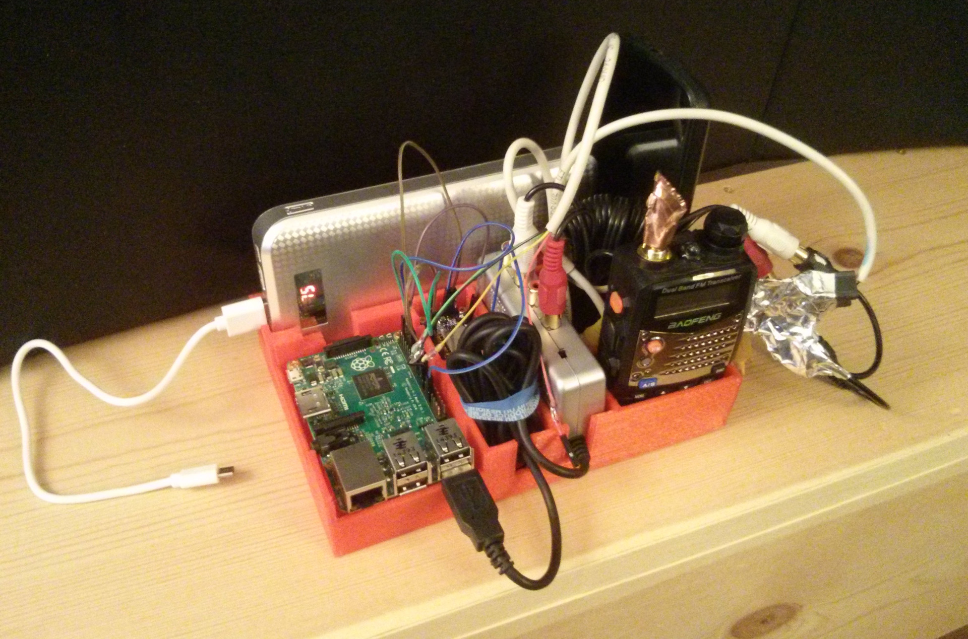
I combined my old PacketRadio interface that used a Raspberry Pi 2, Behringer UCA202 USB DAC, and Baofeng UV-5RA with a second Adafruit Huzzah ESP8266 breakout board and a different USB powerbank that I got as a gift to create a mirror of the packet radio systems in TRILLSAT-1 down to the software level. In version 1.2 of the TrillSat source code, I was able to create a groundstation mode that ignored the power regulation and robotics subsystems of TRILLSAT-1 for TRILLSAT-G. This allows me to test a full over-the-air communication between two mobile TrillSats using two smartphones without having to create a second craft just to demonstrate the test (which would be expensive and time consuming).
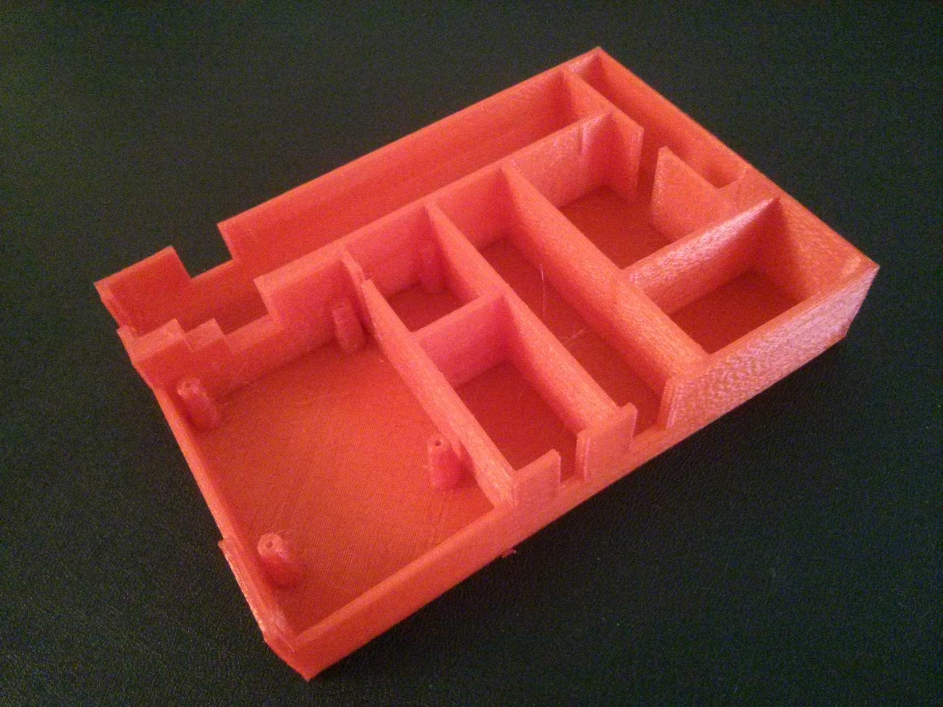
I also designed and 3D-printed a tray using some red PLA filament that I had on-hand, since I didn't want to use the more expensive white PETG as it didn't have to be weatherproof. It holds the equipment together, allows me to mount the circuit boards, and contains compartments for storing the unweildy wires. If the dummy loads are used, the transmitter can remain close to the audio circuitry and won't interfere, but wires are included to allow it to move the radiated power away from unit.
Dummy Loads
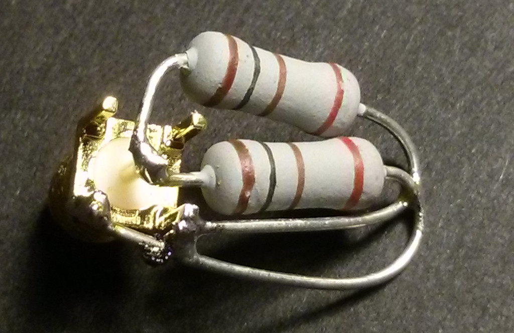
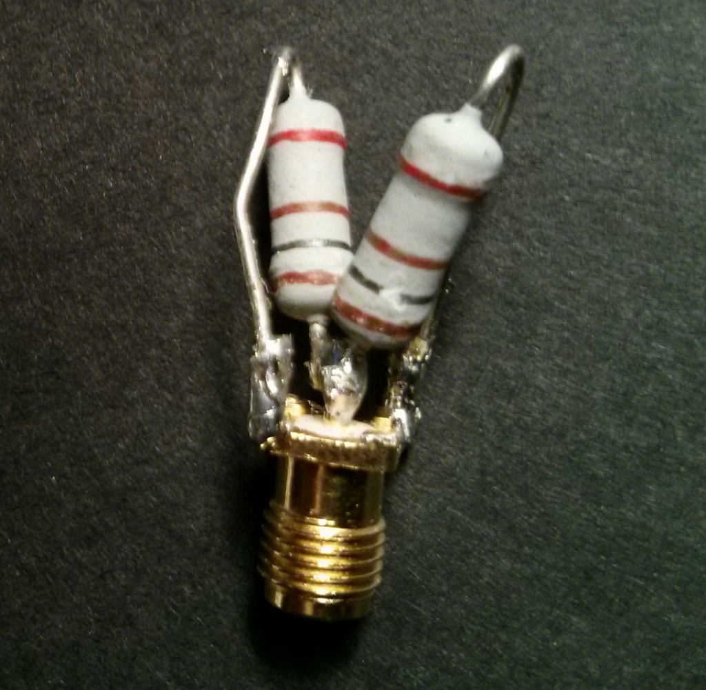
Two 50-ohm dummy loads were constructed using two 2-watt, 100 ohm non-wirewound resistors that I purchased for around $1 from a local electronics store which I soldered in parallel to two female SMA PCB jacks to produce 50-ohm, 4 watts to match the max output of the UV-5RA. I then used Kapton tape as insulation and a copper foil shield soldered to ground.
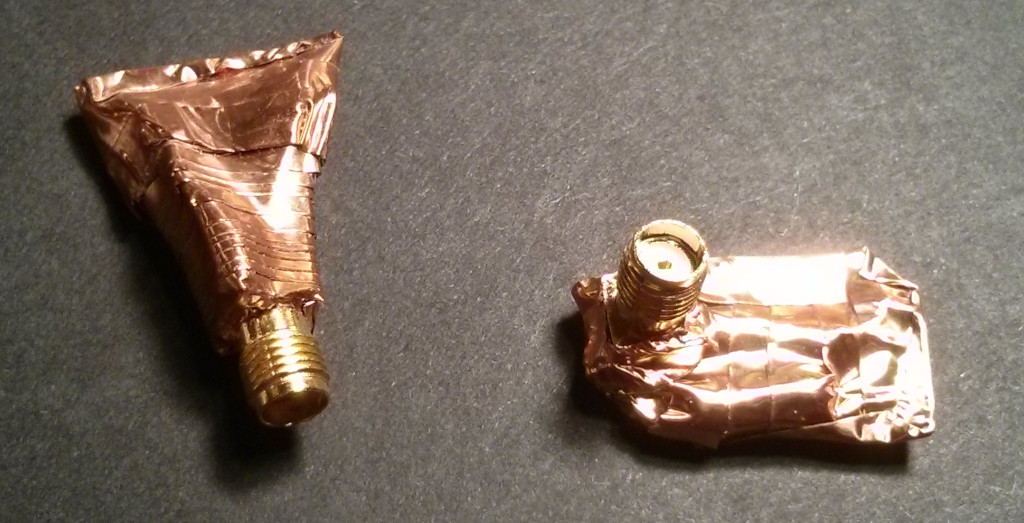
The dummy load for TRILLSAT-G is vertical, but the dummy load for TRILLSAT-1 had to be set at a right angle to fit within the confines of the radio box until I eventually add the external bulkhead adapter to extend the jack outside of the weatherproof housing.
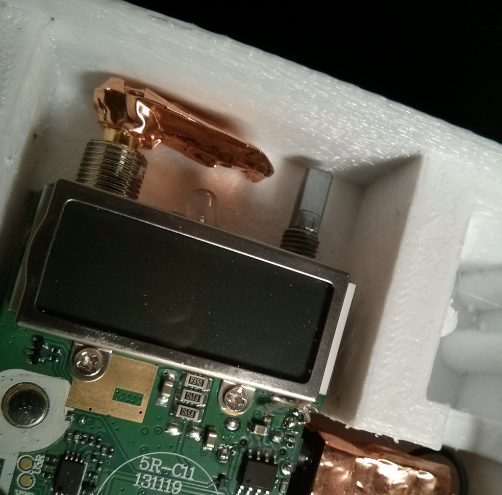
My 4-watt dummy loads are overkill (since I can set the UV-5RA to 1 watt during testing), but I wanted to ensure that it could handle the max power (and heat) in case I forgot to set the power level beforehand. These dummy loads allow me to test the transmissions between the nearby stations a few feet away without bothering other hams that might be monitoring the frequency. Since packet transmissions are in bursts, the dummy loads also have time to cool and they only get warm to the touch. I don't have a field strength meter, but I tested transmissions using this dummy load to a high-gain 2-meter antenna, and after a few hundred meters line-of-sight, the signal was inaudible and had reached the noise floor, so there is some leakage, but it is small.
Video Demonstrations
I've created several videos of the various TrillSat subsystems, such as the XMPP Command System, the haptic system, and the Gyrofan inertial stabilizer, which can be viewed on YouTube here↗. I still need to add additional videos for more subsystems such as motor drive and power regulation systems, but it should at least provide an idea of the scale and behavior of the machine.
Safety
TRILLSAT-1 is an experimental prototype and not appropriate for widespread use without significant improvements. I keep a smoke detector near the unit constantly since the high-current Lithium-ion batteries, in combination with plastic and wood (and a spinning gyro with metal balls) could become a fire hazard in the case of a severe electrical or mechanical malfunction. Even something as simple as a software bug on my part could overload the motors. Moisture, thermal expansion/contraction, or wires that break loose due to fatigue, could cause unforeseen shorts.
The 8.28 lb (3.76 kg) unit is also heavier than I would like and has a low strength-to-weight ratio, and cannot withstand a fall without great damage, and it is also high enough to become a hazard to people underneath it if a branch were to break or the rope were to come loose. Animals could gnaw on the rope, for instance. If the rope detaches from the ground, it would swing toward the tree, and the friction in the capstan might slow its decent somewhat. But if it detaches from the tree-side, it will just freefall straight down. I tried to over-engineer the rigging, rope, and test frame by choosing parts that exceeded the load ratings that I expected, but the quality of some of the parts is questionable. If the unit were to catch fire in the air, the nylon cord would most likely melt above the craft, causing the unit to drop straight down to the ground.
I added some electrical failsafes, as mentioned earlier, and could potentially add high-heat detection and a free-fall audible warning in the future, but designing a complex machine from scratch to be reliable, safe, and robust is really beyond the power of a single individual and more within the domain of large organizations, engineers, and manpower, and years of testing, which is why our modern automobiles and aircraft are so reliable, considering the immense complexity of what is going on under the hood/cowling in conjunction with our natural world.
My late father spent some time in the 1970's working in a refrigeration factory, which, unbeknownst to all of us, was right across the street from a Superfund landfill site containing dumped radioactive waste left over from the Manhattan Project, as depicted in the 2017 documentary Atomic Homefront. Ironically, he used to say to us, "Safety, safety, safety!" He would forgo any design if it wasn't inherently safe to an unwitting user or passerby. I, however, was fascinated by strange, experimental contraptions, but some of his warnings did manage to get through. There was one incident where he cut his hand and had to go to the hospital after catching a heavy toolbox that I almost tipped over onto my head. And I had to go to the hospital myself late one night when I unscrewed the hinges from our old deep freezer, not realizing that springs were compressed inside the hinge... My parents couldn't afford health insurance for us, so my mom had to spend months working to pay off my hospital bills.
Our machines focus energy and mechanical forces to multiply work for us, but such concentrated energy, due to entropy, is always in a precarious, unstable, and potentially hazardous state as it eventually wants to move to a more disorderly state. We can't stop the flow of entropy, but we can warn others and remain alert and nimble enough to step aside and let the worst of it pass.
Completion Status
I've had basic TROT orbital mechanic control over the H-Bridge and planetary drive system via the Hall-effect switches working since 2018, along with basic accelerometer roll and pitch, but have not yet added this to the orbital control to increase precision. Most systems are manual right now, with me issuing XMPP commands, and I have yet to move many of them to pure autonomous algorithms. On April 21, 2020, I decided to calculate the equations of motion (mostly algebraic, a few numerical approximation) and motor torque needed to drive the craft from and to any point on the tether, a higher-level modulation atop the lower-level PWM algorithms, as the craft and mass changes in complex orientation under gravity, which was necessary since it has to predict motion in-between sensor readings and allow the planetary mass to move at constant speed (instead of whipping around erratically or bogging down under load) but have not tested these equations on the motor yet.
The solar charging/voltage monitoring via Huckleberry took priority (since the batteries have to remain charged) and it is autonomous, and it can self-charge but cannot yet work in-conjunction with Sawyer to tilt the panel. Sawyer can read the CdS LDRs but I haven't yet added the algorithm to compute the angle of the sun using light intensity alone or tilt the craft to match this angle.
The haptic system is working on the Test Frame and an EEPROM passcode lock and small set of haptic Morse code commands have been added.
I have not yet constructed the full-sized antenna and am considering a few different designs, including a pendulum mass-damper, although the packet interface and PBBS does work in real world testing over 2 meter using dummy loads. I have full two-way XMPP texting communication (XMPP-to-AX.25-to-AX.25-to-XMPP) over AX.25 Packet Radio (the bug fix for the calling side was completed on March 24th, 2019 and should eventually be added to version 1.2 of the software).
All sensors and closed-loop PWM motor control are working (for both motors) but I haven't yet added the reverse direction to the BLDC (which is fairly simple) so it only works for inertial stabilization and fan in one direction currently. I accidentally burned out the BLDC motor in late March 2018 due to a freak cascade failure when I took it outside in the sun, and have since replaced it and turned on brown-out detection. (I had neglected to turn on the brown-out detection and the flickering sunlight as I was handling it caused the chips to lock-up and the MOSFETs suddenly kicked on turning on the full current and stalling the BLDC motor while also preventing me from using XMPP commands to shut it down. By the time I cut the power lines, the motor had burned up. I do have stall detection in place, but it couldn't activate since the chip locked up.)
The unit has been tested on the Test Frame and can drive up and down the tether and tilt the panels, in both Sign-Magnitude and Locked-Antiphase modes and I matched the speeds of the two modes and added a "Park" command which switches between the modes on-the-fly and allows the "Three-Tridant Orbital Mechanics". The Gyrofan has been tested, fully assembled with the Gyrofan mass loaded to maximum, at 360 RPM, but doesn't have much of an effect at that slow of a speed. After I fixed some bugs in my code in August 2019, I was able to run it at 1800 RPM, but have not yet tested this on the actual tether. I'm not going to increase the speed further until I've at least programmed, tested, and documented the rest of the systems (as I don't want the gyro to disintegrate and damage the rest of the craft.
I haven't yet added an optional camera to the Raspberry Pi Zero W or put an ESP32 LoRa board, battery and Qi receiver in the Space Pod, since I haven't been able to afford them yet (and don't like the idea of adding a camera as I wanted it to represent a communication device and not a surveillance device), but the craft was designed to allow for these units. I'll experiment with the LoRa device in the future if the rest of the systems works well, but I'll need to buy two units, one to act as client.
I published the Full Schematic and Power Regulation circuit, but there are a lot of other systems that really need to be diagrammed and explained when I have time, as it is difficult to understand the design without knowing how it integrates with the software.
In many ways, the system is still a mystery to me. I haven't been able to test it in real-world use yet. I have only taken it outside a couple of times just to get readings on the light intensity. I have no idea how well it will handle an actual tree, wind, etc and how well the antenna will operate at height with changing impedance and near-field effects. It will be an exciting day when it will first announce itself as an experimental system over APRS, and receive its first AX.25 call from different hams, but I haven't gotten to that point yet. Technically, I can put it on the air right now, but I want the caller to be able to access the unit while it is outside on the tether hanging high in the air under solar power, and I want the PBBS to report stats and sensor readings back to the caller.
Significant Problems
Here is a basic list of some of the significant problems/lessons encountered:
- ESP8266 TCP/IP Bridge was slow under Lua
- Calculating weight ahead of time (balance)
- Pausing a packet transmission
- Thermoplastic lack of adhesion
- Friction that works against you
- Importance of fasteners
- Importance of wire gauges and guides
- Proper capstan design
- Wearing out the 3D Printer
- Underestimating switching transistor complexity
- Forgot to account for width of screw heads
- Charging batteries that have to be occasionally placed in series
- Underestimating size of point-to-point circuit board needed
- Used microcontrollers to reduce long wire count
- Used dead-bug wiring instead of through-hole
- Non-linear zener behavior
- Getting enough motor current (via voltage)
- BLDC is not as simple as it seems
- Ground plane isolation issues (didn't use built in boost, even solar panel was isolated)
- Comparator hysteresis
- Raspberry Pi I2C Clock-Stretching Bug
- An entire Test Frame had to be built
- Strange corruption reading 1-wire from Bash launched from Python, but not from shell directly
- Brown-out detection is critical to avoid chip lock-ups that leave MOSFET gates in incorrect states
- Anytime Linux, Android, NodeMCU, or Xabber versions change, I have a lot of work to do to ensure it remains working. Android 6 and later, for example, broke my ESP8266 AP mode in an early version of NodeMCU but when I switched to NodeMCU version 2.2.1-master, it worked again (but the API changed and I had to update my code again). My XMPP code only works with Xabber 1.0.74.
- AX.25 call command was difficult to script due to proper settings and pipe handling
- Math motion calculations to find instantaneous torque for constant motor speed were difficult
Difficulties, Setbacks, and Hindsight
It was next to impossible for me to calculate the weight ahead of time to balance the unit along the tether, so I made some rough, intuitive guesses in my early designs. I knew this might be a problem later but hoped that I could get close. I didn't have access to a gram-metric scale until the project was almost completed, so early on, I hung a few parts on strings, creating a makeshift balance scale, but as the number of parts/complexity increased this became unwieldy and I had to make a lot of calculated guesses.
I initially assumed the Solar Panel Frame assembly (panels, trim, acrylic cover, aluminum backplate) would be as heavy as the rest of the craft (Circuit Boxes, Gondola, drive motor, and Capstan), even taking into consideration the lever/center-of-mass effect of the extended Gondola. The batteries were so heavy, however, that they interfered with my intuition, so I took them out of the equation entirely by placing them directly along the axis. All seemed well in the early stages...
But as I began to design and 3D print more PETG plastic parts, add my circuits, screws, wires, cover panels, motor, Planetary Rod, etc, it started to get heavy and the lower section exceeded the top section by a large margin. The Gyrofan/Fan Duct lowered the Gondola even further increasing the effect. I really didn't know just how well it would work until the project was almost complete (a very unsettling feeling, by the way, since I put 2 years of work into it). I wanted it to right itself automatically, and wanted it to be slightly bottom heavy, but I didn't want it to be so heavy that the Planetary Mass had to be large, or the Planetary Rod had to be long. I originally envisioned a rather balanced craft that stays upright in light wind, and a rather light Planetary Mass to tilt the balance. There is also some tension in the nylon paracord tether that resists the twisting effect, adding to the problem. But the 1 lb Planetary Mass is heavier than I would like.
It turned out that I couldn't run the Gyrofan as fast as I hoped which meant that I had to make it even heavier to have an effect, and the mass increase meant that the gyro mass had to increase, which increased the overall weight (a nasty, multiplicative feedback effect). It reminded me of a similar feedback effect that forced me to add the pulley ball-bearings (as the force needed for the capstan was negated by the guide friction caused by that same force).
Luckily, even with a large Planetary Mass, the unit still has enough torque to drive itself and the weighted gyro, but just barely, and this also required a careful Capstan design. I also thought ahead to use a strong gear system, boosted the voltage and built a powerful H-Bridge and PWM speed algorithms. But this unforeseen weight tends to pull the Planetary Mass away from the Qi Dock especially when near the dock where gravity is perpendicular to the rod, which creates a problem if the Planetary Mass is to one day be replaced by the docking Planetary Space Pod, so I need to make the tolerance even tighter. And the Gyrofan has little stabilizing effect unless it is run very fast or a very heavy inertial mass is added, unless I re-adjust its balance (I'll explain more below). Also, the Gyrofan, when acting as a reaction wheel only, only counteracts the rotation of the capstan drive motor around the z-axis, it doesn't counteract the rotation around the y-axis (since the Gyrofan wheel is symmetrical), so it can cancel some of the unwanted tether sway but not the roll (which is more of an issue). But it does still work as a cooling fan. This is what is good about compounding/overloading functions--if it doesn't do all of its functions well, hopefully it will at least do some of its functions well.
The root of the problem is that my axis of rotation is too high, and it needs to be slightly lowered, placing the batteries above the axis instead of inline, and raising the gyro inline with the axis instead of below. This would remove the parasitic effect of the gyro weights, while at the same time drastically lowering the weight needed for the Planetary Mass (and the overall weight), allowing the craft to hang higher in the air. It also reduces the strain and current requirements of the craft and allows the gyro to exert an appreciable effect.
Without a major rebuild of the craft (weeks/months of work), this could be achieved by a few relatively minor modifications:
- Print two shim layers that fit atop the Radio and Power Regulation Boxes, lowering the tether axis. These shims will have to be strong enough and securely mounted to handle the force of the tether, and the tether holes will have to be sloped to allow the tether to slide smoothly at that angle.
- Print two new Braces to replace the existing ones, lowering the tether holes, again, sloping them so the tether meets the pulley at the correct angle.
- Drill a hole into the Planetary Mass and remove unnecessary weight, then seal up the hole.
Operating it at these excessive weights, however, was fascinating in a way, as it forced me to find the limits of the structure, motor and motor algorithms. It also caused me to discover new things. For example, I discovered that the energy needed to lift the heavy Planetary Mass against gravity is not entirely wasted, as it is recaptured when the weight descends and helps to propel the craft. I might have never have noticed this relationship (or thought it was significant) if the weight wasn't exaggerated enough for me to recognize it.
If I do re-balance it properly in the future, I'll have more than enough power. A heavy plastic craft (8.28 lbs, 3.76 kg) also makes it fragile, easy to break in falls, easy to smash if it runs into walls or branches, easy to crush when grabbing and moving it. I used 20% honeycomb infill in much of the prints, but I should have printed more voids and used 15% infill.
But perhaps the most concerning aspect of a heavy craft is that it can defeat the whole design if it gets past a certain point due to the vector force equation of a weight suspended between 2 ropes (which is essentially what happens at the edges of the Solar Panel Frame assembly). The catenary shape begins to exaggerate, and as the weight increases, the tension at the ends needs to pull at a force greater than the weight of the craft. If the craft is light, this is no problem, as the rope can be tensioned to raise it to a high angle, since such a tension can be several times the weight of the craft. But you can't tension a rope several times the weight of a heavy craft without putting too much strain on the ropes, plastic frame, pulleys, capstan, and motor. So each pound or kilogram you add to the craft makes it droop lower to the ground. On the Test Frame in Frame Mode, it "looks" okay, but this angle (which remains constant regardless of the length of tether) would be pretty large in actual use.
As the craft approaches the tree, it does raise much higher, transferring more force to that "rope" (that particular side of the rope), but this changes the angle to the sun drastically and puts more strain on the Capstan and motor. So to get a heavy craft high enough for good radio propagation, you need to secure the rope to the top of a very tall tree and anchor it to the ground very far away, and such a long tether creates its own problems such as increasing the sway time (pendulum period) and consuming a lot of power to traverse a long length of rope.
I used Pi and trigonometry heavily in this project, as it is a rotational, oscillating machine that has to be in alignment with a rotating planetary system (our Sun and Earth), and I am deeply captivated by rotating mechanisms, like the beautiful space ports and ships in Kubrick's 2001: A Space Odyssey and have written about the curious relationships between TheCircleAndTheLine.
But this problem gave me a greater appreciation for the constant e, which I hadn't thought much about since my abstract mathematics classes. I live in the city of Eero Saarinen's Gateway Arch, a beautiful stainless steel, inverted, weighted catenary which is based on what we call the hyperbolic cosine, the shape that a hanging rope assumes under gravity. I ended up having to use various hyperbolic cosine curves with different coefficients and multipliers to approximate different situations of the hanging tether, but since OpenSCAD lacked the hyperbolic math functions, I decided to construct the parametric equations using various powers of e, which brought this relationship to my attention. I also had to use its derivative (which turns out to be the hyperbolic sine), dredging up my old Calculus memories, along with the arctangent to perform the angular rotation.
The hyperbolic cosine and sine aren't really trigonometric functions at all, not based on the unit circle, but are based on the hyperbola and e, another irrational, transcendental number like pi. Yet, strangely, there is a relationship to pi and trigonometry through imaginary (complex) numbers. This relationship is fascinating and mysterious to me, like the fractal Mandelbrot Set, which is also based on the complex plane.
This is perhaps best shown in Euler's Identity:
e iπ + 1 = 0
Astounding.
Conclusion
Fractal Characteristics
As I mentioned earlier, the design of the craft is fractal in many ways, but I didn't realize until after the thing was built, just how fractal it was, and the comparisons/analogies are interesting. Here are some of my observations:
- Firstly, the trill, or warble of the digital sound it makes, is also a metaphor of the craft's motion as it oscillates left and right, as mentioned earlier, although much slower in time. The word trill can also mean to vibrate or roll (oscillate).
- Planet earth orbits the sun, influenced by gravity, which provides wireless power to the craft, and the Planetary Mass orbits the craft, influenced by gravity, driven by a powered capstan (mechanical power) but it also provides electromagnetic power to a future Planetary Space Pod (Qi Dock) similar to the sun's gravity and radiation. And inside the motor housing that drives the planetary assembly is the screwdriver's own planetary gearbox↗. Orbits within orbits.
- The craft is also composed of a series of shapes within shapes (rectangles within rectangles, and circles within circles):
- The rectangles contain inset rectangles, sometimes "boxes", within them that house the actual circuit boards and devices, like an upside-down ziggurat. These "boxes within boxes" are ultimately housed in a wooden storage box, the Ark.
- The Test Frame is a mast that is balanced by tethers on both sides (one is steel, one is nylon) converting much of the force downward, to compress the mast, and within one of those tethers is a Gondola, a smaller inverted mast, that is balanced by tethers on both sides converting much of the force to compressive.
- The tension in the tether between the tree and ground lift the craft upwards, but the tension between the Battery Frame pulleys lifts the Gondola upwards, and the tension between the Pulley Frame pulleys lift the Planetary Assembly upwards, nested sections of lifting tethers.
- The Battery Frame has a round, Fan Duct inset, inside of which is the spinning Gyro wheel, inside of which are spherical steel balls. Attached to the sides of the battery frame which contains this duct, like the bulbs on the Mandelbrot set are 2 circular pulleys which also contain more steel balls. And orbiting this whole assembly is a spherical planetary mass that contains more spherical steel balls. Note that the planetary mass is, more accurately, a sphere with a flattened side and the Gyro wheel masses are tiny spheres with flattened sides.
- The Radio relies on the Pi, the Pi relies on the ESP8266, and the ESP8266 relies on the two ATtinys, in order of function.
- The craft is a high-level collection of switching circuits, MOSFETs/relays, which are in turn controlled by mid-level bipolar junction transistors, which are in turn controlled by low-level microcontrollers (which are themselves collections of switching transistors). I even chose to "switch out" battery banks instead of perform pass-through and series charging.
- The craft is in large part a construction of the de-construction (re-purposing) of consumer products. I write about this concept in UnityAndSeparation.
- As I alluded to above, the craft sits at the intersection of pi and e, circles and hyperbolic curves, the orbits and the catenary, in binary oscillation, and curiously the master CPUs are the Pi and ESP.
- The craft can allow peer-to-peer (self-similar) communication with other crafts like itself, extending its range.
- The craft can connect to an existing WiFi access point, but when one is not available, it will become its own access point (slave becoming master, an order transition).
- There are both low and high programming languages (C, Lua, Python 2/3, Unix/BASH) used at various abstraction levels of the craft's function.
- The unit can program itself in-circuit (recursion). A user can remotely program the code on the Pi, ESP and the ATtinys while maintaining partial operation.
- The unit can also recursively bootstrap itself: On a daily cycle, the sun provides power to an ATtiny which can in-turn activate its own battery power (or a manual bootstrap switch can be pressed), and the battery power then keeps its switch turned on unless this cycle is broken. A similar bootstrap mechanism allows the Pi to keep itself turned on (but the ESP can break the cycle via the Pi reset switch).
- Think about the early days of wired telegraph: Morse code transmitted along overhead wires. The advancements made possible due to such long-distance, instantaneous communication allowed a craft like this to exist, which in turn can detect Morse code while hanging on an overhead tether (via several orders of technological abstraction, and centuries, later...) It takes something old (Morse) and presents it on something new, but then does it in an even older fashion (physical tether vibration).
- There is a hierarchy of radio signals and distance: If you're closest, you can use the Morse protocol via light beam or tether vibration, if your farther away, you can use the WiFi radio (XMPP), if you are a few kilometers away, you could use the experimental LoRa Planetary Space Pod, if you are many miles away, you can use the 1 or 4-watt 2-meter AX.25, and finally, an APRS transmission could even be captured by nearby repeaters and repeated over great distances.
- The LED light can only be controlled by the lowest-level chips when the highest-level chips fail (or allow it), a nested fallback mechanism. If the Pi fails, the ESP can gain control over the light, if the ESP fails, the ATtinys can gain control over the light.
- There is a dualistic, yin-yang cooperation of the two ATtinys: They can achieve almost the same goals independently if the other ATtiny fails, but with worse results--only in union, or cooperation, do they become greater than the sum of their parts. Sawyer controls the motors and can sense and tilt to the sun, but not use the batteries, while Huckleberry can sense the electrical power coming from the sun and control the batteries. Both can detect sudden movement, but in different ways (Sawyer via the inertial gyro Hall-effect sensors, and Huckleberry via the accelerometer interrupt) and both can receive Morse Code (Sawyer via the CdS cell, and Huckleberry via the accelerometer interrupt).
- The craft includes its own "effigy", a smaller version of itself. The Planetary Space Pod or smartphone "docks" underneath another hanging rectangle, the Qi Dock, but coincidentally, this rectangle looks a little bit like a sci-fi shuttlecraft already "docked" underneath the mothership, as if there is nested docking taking place. And the Planetary Space Pod is like the pod in 2001: A Space Odyssey docking with an elongated Discovery One mothership. In fact, the dock could be thought of as a mini inverted representation of the entire craft, as instead of receiving power from its overhead solar panel, it emits power from its underlying Qi charger. I had some room left over, which happened to be the best orientation for 3D printing text, so I printed the word "TRILLSAT-1" into the dock to solidify its place as an effigy of the main unit.
- Things that seemed like they would cause difficulty in practice turned out to have the reverse effect:
- The housing is 3D-printed "upward" but the craft is oriented "downward" and the constraints on printing successfully work to the benefit of allowing water runoff (when inverted).
- The catenary friction on the guides at the ends of the craft is not a problem since the tightening of the capstan tether at the driving end straightens the catenary, reducing the friction.
- The Gondola unit, batteries, and battery cover, which fall under gravity, is actually held in place by the upward tension of the tether, the bolts do very little mechanically, but are great for high-current, external access.
- A tight tether, while adding great stress to the frame due to the weight of the craft, adds friction which helps the Capstan gain traction, and the forces are mostly equalized on both sides, nullifying many unwanted forces.
- A sagging tether isn't a problem either, as it creates a catenary curve that allows the solar-tracker to adjust angles for time of year.
- The Battery Frame, which has to be strong, and thus rather heavy, to hold the Solar Panel Frame together, is also strong enough to withstand the tensile forces of the tether at the pulleys, and is strong enough to create a shield in case the gyro disintegrates, a convenient coincidence.
- The flat surface that is required for the planar Qi coil on the Planetary Space Pod provides a stable base for printing the upper portion of the Planetary Space Pod sphere.
The Never-Ending Maze
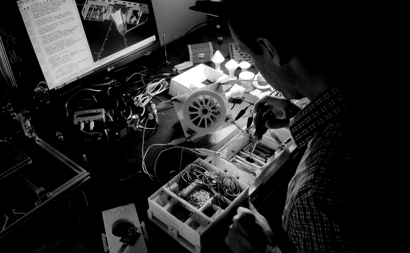
This was an amazing project that will take me years to understand, improve, and integrate into my mental constructs. It's a treasure chest in the middle of a long maze, a chest full of knowledge, revealing mathematical and philosophical principles in ways that I hadn't considered, and the maze itself, the path to the treasure, is also etched with knowledge and notes in a foreign language, a language so advanced that I will never fully decode, but I try very hard to glean fragments. Just the fact that things like this can even exist fascinates me, that the Universe works with such precision to allow our assemblies to exist, that Mankind can build integrated circuits and machines with such precision, isolate natural laws into terse, symbolic equations, create all manner of cyclical engines that run on energy, and that our society provides the bounty of these endeavors to individuals. There is no dearth of knowledge in this world; even if you are isolated, the act of creating things is like a shortwave radio tuner, and the programming is never ending.
"But please remember: this is only a work of fiction. The truth, as always, will be far stranger."
-excerpt from Arthur C. Clarke, 1968, in his foreward to 2001: A Space Odyssey