↑ DeadPiAudio
Page Created: 11/30/2019 Last Modified: 6/6/2022 Last Generated: 7/27/2026
Resurrecting a Burned-Out Raspberry Pi Model B to Add Audio to a Raspberry Pi Zero
(With 2-Channel Mute!)
(Please note that I am not an audio engineer and have created this project for my own use only, providing information about it in the hopes it will be useful to others in some way. It might not be suitable for you, and I am not responsible for the correctness of the information and do not warrant it in any way. Also note that I created this project before I knew about the newer sigma-delta modulation mode, described in more detail below, which may reduce its usefulness.)
- Introduction
- Construction
- Connection and Configuration
- Muting the Left and Right Channels Independently
- Hindsight and Conclusion
Introduction
In 2019, my trusty and only RaspberryPi 3 spontaneously combusted. It was probably due to an insect inside my monitor that shorted out the power, and it left me without a substitute, so I began looking at moving my Pi 2 which was used in my PacketRadio project to the task, but this required swapping out that Pi 2 with a Pi B+ which was used by my OswaldCluster project, but to replace the B+ all I had left were the non-wifi Pi Zeros, which led me to an epiphany, and I swapped out three of the Pis in OswaldCluster with Pi Zeros to improve power usage, cost, and performance. The only problem was that the Pi Zero had no voice, no built-in audio jack for speech or music.
With today's integrated technology, audio is trivial and the Pi Zero provides several different options: external USB audio device, HDMI audio out, I2S interface, and PWM audio. But I could not connect my old USB audio adapter since I was running the Pi Zero in "USB Ethernet Gadget" mode which prohibited me from attaching a hub, and I didn't want to connect it to another server and stream it over IP. HDMI audio and I2S interfaces were too expensive for me, more than the $5 cost of the Pi Zero itself, and so I looked into building a small audio filtering circuit to replicate the functionality of the previous Pi B that it replaced. Many people have published articles explaining how to build this circuit since the Pi Zero was released in 2015. The schematics for the Pi Model B audio filter circuit were released by the Raspberry Pi Foundation in 2012↗, and the electronics are easily replicated using four resistors (two 150 ohm, two 270 ohm), four capacitors (two 10 uF, two 33 nF), and a 3.5 mm headphone jack, under $5 in total for me.
So I went to my favorite local electronics store↗ to get the parts but saw a sign on the door that said they have relocated to a mall many miles farther away from me, and the cost of the round-trip gasoline was now more expensive than the parts themselves. Frustrated, I tried scavenging up old parts that I had on hand or parts from my old motherboard that burned out in March 2019 and was able to retrieve most of the resistor and capacitor values, but not all.
A neat thing about resistance and capacitance is that if you don't have the exact value you need, you can derive it by placing many different components in various combinations. Resistance is additive in series, but in parallel it is the "reciprocal of the sum of the reciprocals of all resistors". Conversely, capacitance is additive in parallel, but in series it is the "reciprocal of the sum of the reciprocals of all capacitors". This is made even more useful when you consider that the values often sold follow an E series↗ logarithmic sequence that allow desired values through their combinations.
I was able to come up with the resistor values, and the 10 uF electrolytic capacitor was found on my old motherboard, but the 33 nF was surprisingly hard to find and the closest I could come up with was one 22 nF.
Even if I could find two of them, that 22 nF value was not close enough for my liking, since in that RC circuit, that capacitor is critical in determining where the frequency cutoff is for the audio filters (which is around 18 kHz in the original circuit), and this would allow higher frequencies to pass, potentially adding noise to my system.
But while I was looking through my e-waste pile for boards to find those parts, I saw the colorful, blue 3.5 mm audio jack on an old, Raspberry Pi model B that I had damaged back in 2014 and came to a realization: that burned-out board not only contains the 3.5 mm audio jack that I need but contains those exact resistors and capacitors that I need, surely still in working order. They were far too small for me to remove, but could I simply leave them in place and tap into that circuit directly?
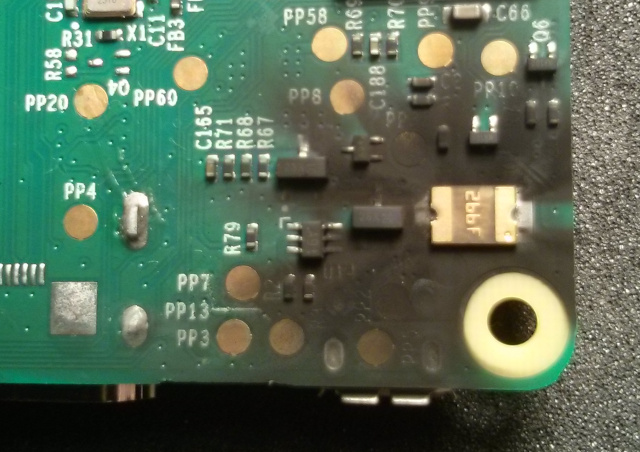
The SMD component sizes on the top of the board are very tiny and appeared to have dimensions of 1mm or less, probably 1005 packages:
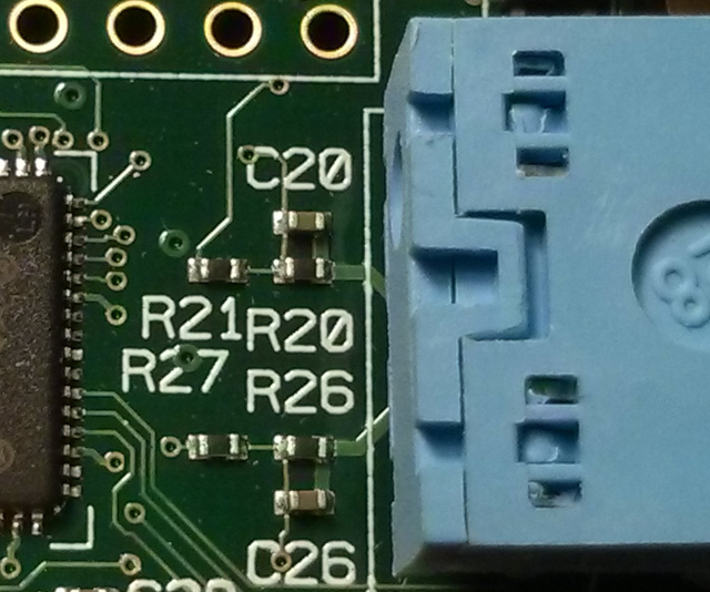
When you look at the board, this circuit has some beneficial characteristics for this application. It is a multilayer PCB, but the surface layers aren't highly embedded within other circuitry, allowing it to be accessed with a multimeter without removing the components. One end is connected to the audio jack (which is an open connection until an audio plug is inserted), and the other end is connected to a powered-down BCM2835 on GPIO40 (PWM0_OUT) and GPIO45 (PWM1_OUT). According to the datasheet, all GPIO pins go into input operation on reset, and input mode on many microcontrollers is usually high-impedance, so I assume that the pins go into a high-impedance or floating mode when powered down. This means that, as long as the board is powered down, I can interface the Pi Zero's PWM lines directly to resistors R21 and R27 and use that audio circuit independently of the rest of the Raspberry Pi board.
The circuit on the Pi Model B is small and passive. On the top of the board, you can see the RC audio filter circuit. I was even able to fit my multimeter leads in to measure 270 ohms on R21 and R27 and 150 ohms on R20 and R26 just like the schematic. However, my capacitor measurements of C20 and C26 were slightly smaller, as I was measuring them in-circuit and stray series capacitance from the wires or test leads could have reduced the value. But since I had two of them to test, I could confirm that their values matched each other and were therefore likely undamaged. One thing I forgot to test beforehand was whether the left pads of R21 and R27 (the lines that actually connect to PWM0 and PWM1, respectively, on the Broadcom BCM2835 SoC ARM chip) were left in an open circuit and were not shorted out inside a potentially, heavily-damaged chip. In my case it worked fine, but it would have been a good idea to use the ohmmeter function to make sure there is still high-impedance between those resistors and ground (see the photo in Step 4 below for the location of the solder pad where I attached the ground connection on the bottom of the board) so that the audio from the Pi Zero isn't shorted to ground.
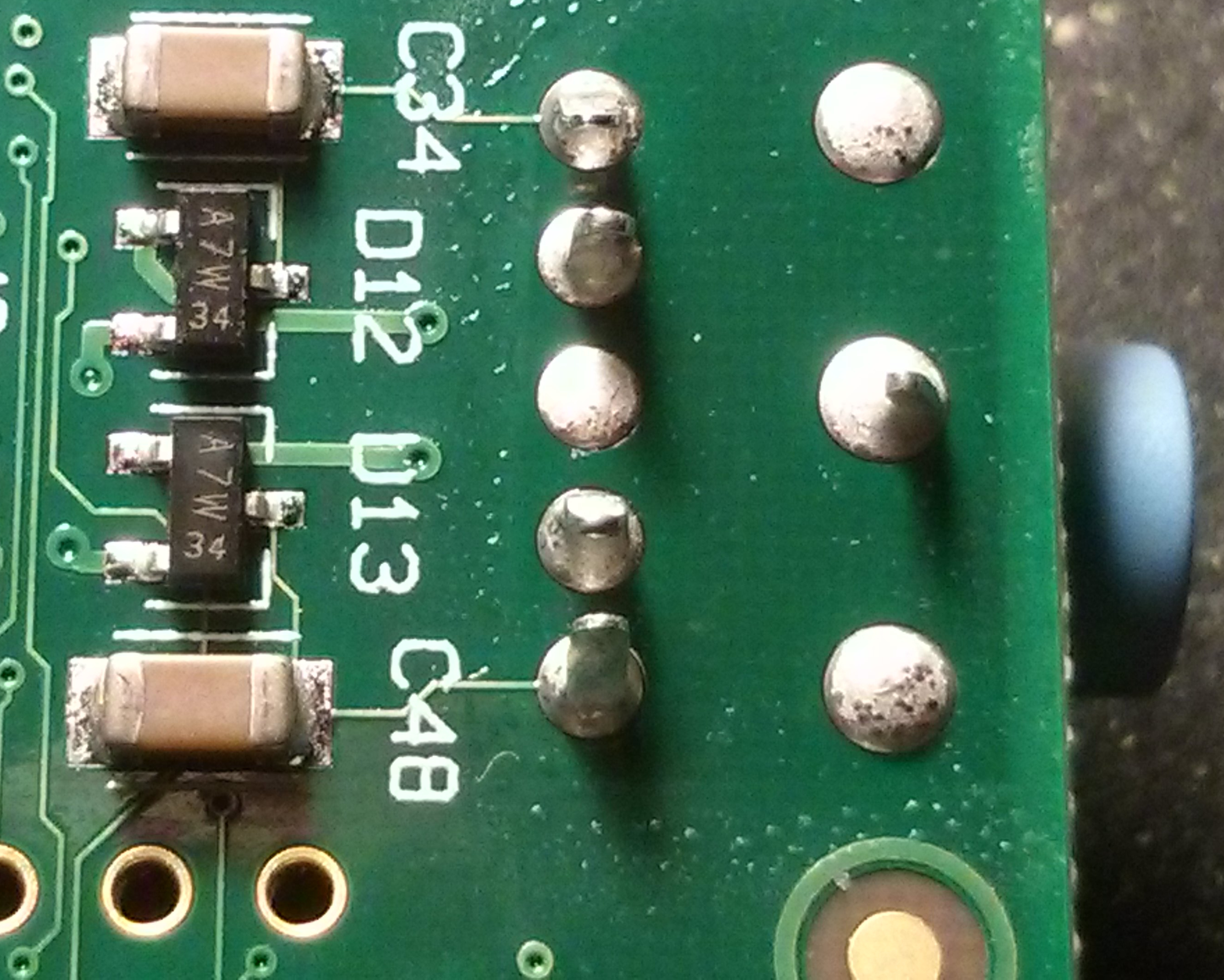
On the bottom side, C34 and C48, the larger 10 uF capacitors, are clearly visible along with the powered ESD protection diodes. I decided not to replicate the protection diodes and avoided sending 3.3 volts to the board. I just needed that passive RC audio filter.
While those resistors are extremely small, I was able to solder wires to them due to the wide spacing on the board and preparing the area beforehand. Two photos above, you can see that the left edge (where I need to solder) on R21 and R27 is essentially free of obstruction, and they are close to the audio jack and almost symmetrical, the top R21, R20, C20 forming the right channel (PWM0) and the bottom R27, R26, and C26 forming the left channel (PWM1). The bottom side is similar, being close to the audio jack directly underneath. After I completed this circuit, I realized that the circuit seems to be self-contained above and below the board, and this rectangular section might be successfully removed to make it smaller. However, it is a multi-layer board, and I could not see the traces underneath. It was also too risky for me to try to cut or saw it out after the fact. Since I'm not using the diode assembly, the only line I need to worry about cutting is the ground line, which appears to be shared directly with the ground line on the jack itself. Great!
Construction
First, I got out my legendary dirt-cheap Radio Shack 30-watt soldering iron. It is around 3-decades old, is still in regular use by me, but for some mysterious reason has never burned out like the soldering irons before it (which were the same brand and model). It is my own tiny, magical, Beast Spear↗.
But, like the dual-edged Beast Spear, is has a dual nature, as I found out several years ago when I went to the hospital burn center one night after it fell off my desk and my quick (too quick) reflex was to catch it in mid-air with my bare hand... the wrong end. Needless to say, I have since purchased a soldering iron stand.
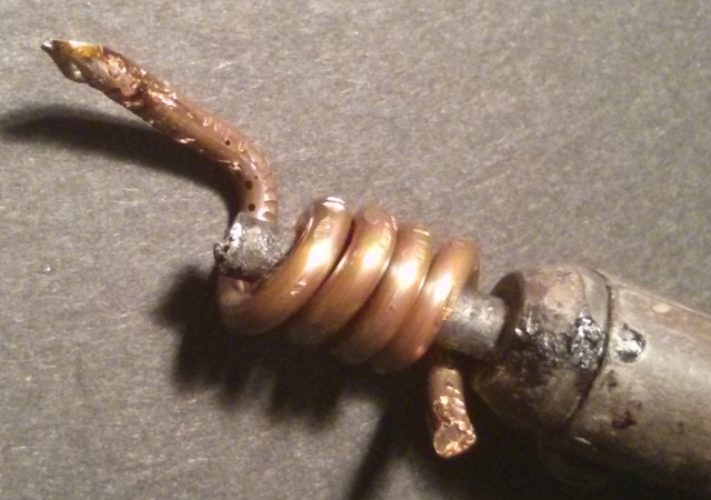
Anyway, I can't find new tips for it, and it has a gigantic blunt tip that would be absurd to attempt to use to solder to those tiny SMD resistors, so I removed the insulation from some 12-gauge electrical wire and coiled it around the cold tip, compressing it with pliers, and then I snipped off the end with wire snips to make it sharper. It is still big, but not nearly as big as the old, flat soldering iron tip. But it doesn't get as hot as the main tip so I have to hold it against the part longer.
I had previously used this coiled tip to solder circuitry for my TrillSat project but had never intended nor attempted to use it for SMT devices this small.
I also used a magnifying glass desk lamp to view the part while soldering since it is tiny and hard to see. However, I couldn't see the snaking AC power cord of the iron as it curled up while looking under my magnifying lamp and accidentally melted through the insulation (an electrocution hazard). Luckily I could smell the (probably hazardous) fumes and realized my mistake before it reached the wire itself. Whew!
Sometimes the Beast Spear has a will on its own. A high-temperature silicone cord is next on my list...
Step 1 - Glued a Stable Jumper Platform
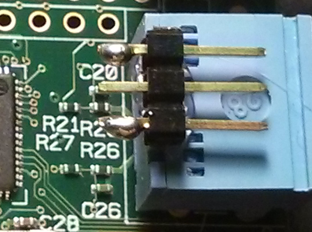
First, I put some solder blobs on a row of 3 jumper pins and hot-glued them to the jack as shown. Note that it might have been better to use a rigid epoxy glue (see step 5 below for more information on this). Because the left and right channel circuits are symmetrical on the board and spaced in that way, these jumper pins provide a nice platform for simple vertical wires between themselves and the resistors.
Step 2 - Prepared Some Short Wires and Soldered to Jumpers
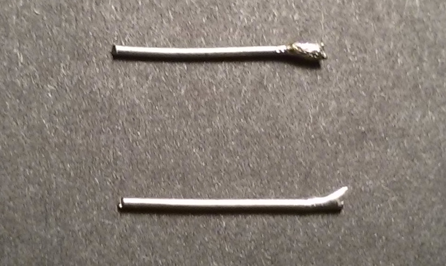
Then, I cut some tiny leads from an old 1/4 watt resistor (but any thin wires would do) that fit between the resistor and the jack pins and then applied a tiny bit of solder to the ends. I did this ahead of time, since it was too risky to apply a relatively huge blob of solder at the time of soldering due to the tiny resistor size.
I also cut a short ground wire, soldered it to the middle pin and hot-glued it around the jack to reach the bottom of the board. (I probably should have done this before I hot-glued the jumpers but didn't think about it.) Then I used needle-nose pliers to hold the tiny wires (with the cold solder blob end resting on the board against the left side of the resistors R21 and R27) while I soldered the top of the wires to the jumper pins by melting the solder blob that was already on the jumpers.
Step 3 - Tensioned Wires and Soldered to SMT Resistors
Starting with resistor R21, the key was to carefully bend the wire and/or push down on the jumper assembly to allow the springiness in the wire itself to naturally push against the left edge of the resistor. This ensured that all I had to do was heat the bottom end of that wire containing the cold solder blob to allow that blob to melt against the left solder pad of that resistor. I had to hold the iron in place long enough to ensure it made a good solder joint, but not too long or I could have desoldered the entire resistor, which would junk the board (but I had already considered the board junk to begin with, so it was just a bonus if I was successful).
Then I repeated that procedure for resistor R27 with the other wire and jumper pin.
Step 4 - Soldered Ground Wire to Bottom of Board
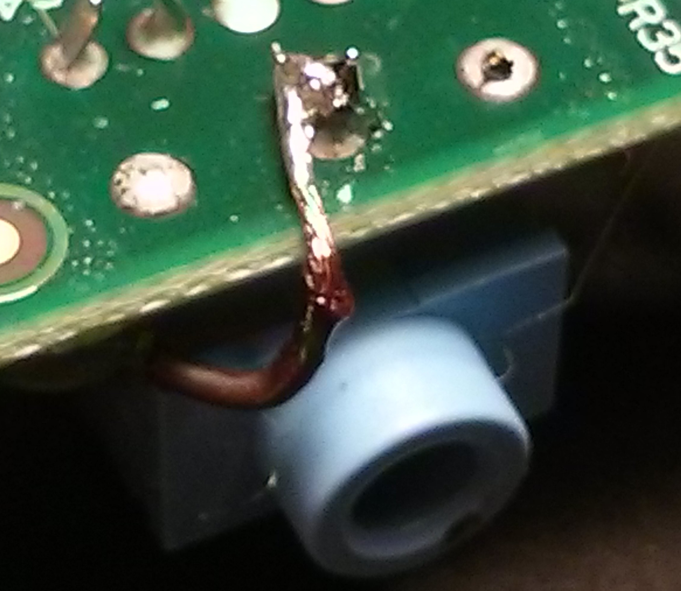
Finally, I soldered the other end of the middle wire to the ground terminal of the jack as shown on the bottom of the board.
At this point, the interface was electrically complete and could be connected to the Pi Zero using standard GPIO jumper wires, since I've already soldered GPIO header pins to the Pi Zero beforehand. The Pi Zero WH already comes with headers soldered, but this is not the case for the Pi Zero.
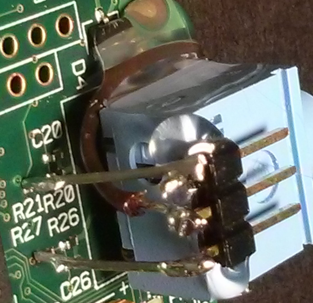
Step 5 - Covered Jack With Glue
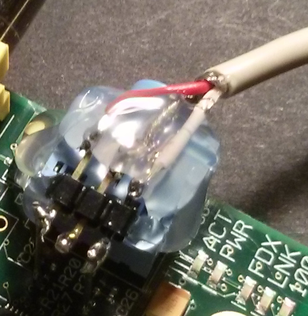
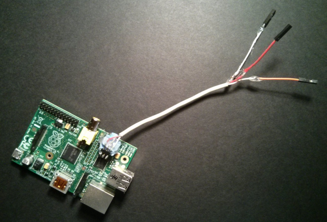
However, I discovered that it was too fragile to plug in the jumpers without possibly breaking off the wires from the resistors since the jumper rocked slightly as I connected the jumper wires to the jumper pins. So I decided to forgo using the jumper pins as jumpers and soldered an audio cable right wire (top, red) and left wire (bottom, white) directly to the jumper pins, with the shielded ground wire in the middle, and then covered the whole thing in hot glue to ensure that it was as secure as possible. I had to be sure to avoid clogging up the jack itself or injecting glue into the holes. I then soldered jumper wires to the ends of the audio cable, but I ran out of colors for the ground wire, so I decided to use red and orange for right and left channels, respectively, and white as ground, but it would be better to use red and white for right and left, respectively, and black or green as ground if I had the choice.
Even though I chose not to use the jumper pins as actual jumpers, they still acted as a nice soldering platform that would be otherwise difficult. I used a lot of jumpers in this way on my TrillSat project, for example.
Connection and Configuration
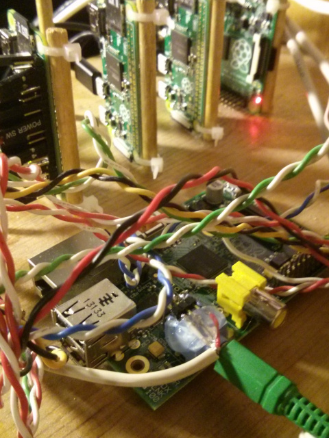
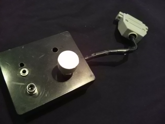
Here you can see the actual Dead Pi Audio board in use, and it works! You can't clearly see the connection to the Pi Zero in the photo, so I'll explain below:
The Pi Zero has no traditional audio jack like a Pi B (or even a Pi B+, which is slightly different), so it cannot use the ALT functions of GPIO 40 and GPIO 45 to connect to PWM 0 and PWM 1, respectively, which is how a Pi B works internally as shown in the aforementioned schematic. But on the Pi Zero, these PWM channels are exposed on a few other GPIO ports, as long as you set the ALT mode correctly.
This eLinux wiki page is a great source of information about the Raspberry Pi GPIO pins and their alternative functions:
https://elinux.org/RPi_BCM2835_GPIOs
I decided to use GPIO12 for PWM0 and GPIO13 for PWM1, since these ports lie at the bottom of the GPIO header on the Raspberry Pi Zero and did not interfere with the other circuitry that I already had connected to the top of the header. These are both under ALT0 mode.
So I connected the red wire in my interface to GPIO12. My Pi Zeros are oriented so the SDcard is on top and the GPIO is on the right, and the 5TH GPIO pin from the bottom on the right column is GPIO12. The GPIO pinout can also be found here:
https://elinux.org/RPi_Low-level_peripherals#Model_A.2B.2C_B.2B_and_B2
I connected the orange wire to GPIO13, which is the 4th pin from the bottom on the left column. Then I connected my ground wire (which in my case was soldered to the common ground shield on my audio cable) to the bottom, left GND pin on the Pi Zero GPIO.
Before audio can be enabled in the Pi, to enable the kernel module, I had to add the following to my /etc/modules-load.d/raspberrypi.conf file in Void Linux:
snd-bcm2835
And I also added the following lines to my /boot/config.txt file:
dtparam=audio=on
dtoverlay=pwm-2chan,pin=12,func=4,pin2=13,func2=4
All the dtoverlay line does is ensure ALT0 mode on GPIO ports 12 and 13 is enabled on bootup, but this line isn't really required, since I can always manually use commands in the popular WiringPi package (which I had already installed via pacman -S wiringpi). For example, the command sudo gpio -g mode 12 alt0;gpio -g mode 13 alt0 does the same thing after boot, which I will elaborate on below.
However, after an update in 2020, my ALSA device was suddenly no longer detected in my Arch ARM Linux Raspberry Pi installation (which I later moved to Void Linux in 2022), and it took me until 2021 to figure out what had happened: a new dtoverlay option called "audremap" was added specifically to handle this situation. So for newer firmware, I have to use this line instead of the pwm-2chan line:
dtoverlay=audremap,pins_12_13=on,enable_jack=on
While researching this problem, I also discovered and enabled the wonderful sigma-delta modulation mode which leverages the GPU to increase fidelity to CD quality sound:
audio_pwm_mode=2
Then I rebooted.
Muting the Left and Right Channels Independently
At this point the Pi Zero is ready to output audio, and as long as ALSA is working (and alsa-utils had to be installed with pacman -S alsa-utils) and no other sound cards are installed, it was just a matter of doing something like this to output an audio test tone:
Test left channel:
sudo speaker-test -t sine -f 440 -c 2 -s 1
Test right channel:
sudo speaker-test -t sine -f 440 -c 2 -s 2
The Raspberry Pi Zero (and Pi B and B+) do not have the ability to control the hardware volume of the left and right channels independently though mixers such as alsamixer as is typical of a normal stereo audio card. There are other limitations, too, such as being limited to 11 bits (but the newer sigma-delta mode, mentioned above, can now overcome this). These were the reasons (along with a popping noise) that I did not use the Pi B built-in audio in the first iteration of OswaldBot, my home automation server, as I would have loud pops in different rooms, and I wanted to put some rooms on the left channel and some on the right so that I could direct sound around through part of my landline phone wiring (which was not connected nor being used) using a 22 Watt TDA7360 stereo audio amplifier chip (salvaged from an old PC speaker system) without the need for additional circuitry. Bluetooth audio was also expensive at the time.
The pops were very annoying as they occurred in speakers in every room, and this was a known issue in the early Pi firmware years ago↗, because there was a slight voltage difference that occurred when PWM was switched in and out. So, for example, I would play a sound at night on the left channel (which went into certain rooms), the rooms with the right channel would suddenly pop as well, even though they played no audio. This was because the audio device would shut off the PWM connection after it was released. And once shutoff, any new sound that is played will have to turn it on again, creating the pop in all rooms. A later firmware update seems to have corrected the shutoff on device release, leaving PWM enabled so that future sounds would not create the pop. But again, they would play on both channels, since the mixer could not mute the channels independently.
But after working with this project, I realized that even though the audio channel hardware volume must be the same for both the left and right channels (unless I used a software solution like ALSA softvol or PulseAudio, which I didn't want to use), by controlling the GPIO lines in real-time, independent left/right muting can be achieved to allow such a system to work while also keeping any popping noise confined to the channel in use. Once PWM is disabled on a single channel, for example, it stays disabled.
On my Dead Pi Zero interface on the Pi Zero, using WiringPi, to mute:
sudo gpio -g mode 12 input (right channel)
sudo gpio -g mode 13 input (left channel)
To unmute:
sudo gpio -g mode 12 ALT0 (right channel)
sudo gpio -g mode 13 ALT0 (left channel)
On a normal Pi B, it is slightly different. To mute:
sudo gpio -g mode 40 input (right channel)
sudo gpio -g mode 45 input (left channel)
To unmute:
sudo gpio -g mode 40 ALT0 (right channel)
sudo gpio -g mode 45 ALT0 (left channel)
Muting disconnects PWM from those GPIO lines and sets them to a high impedance mode to stop the audio. Note that on the Pi model B, the GPIO pins are not exposed and so WiringPi does not show them when using a "gpio readall" command, but it can control those pins, nevertheless.
So if I decide to mute just one channel, I can continue to send audio to the other channel as needed without any pops or audio on the other channel since PWM is completely disconnected. This keeps the silent rooms silent until I need to send audio to them. Great!
Hindsight and Conclusion
Severing the connection to the BCM2835 chip through the tiny, circular vias↗ with a utility knife might be advantagous to ensure there is no distortion of the signal to get maximum fidelity and also ensure there are no sinks to ground. The thin traces connecting the left pads of R21 and R27 to those vias need to be cut to ensure they don't connect between the layers and reach the chip, but since they are so close to the left resistor pads, this makes soldering more difficult (as the solder blob could cover the vias). After cutting the traces to the vias, but before soldering, I need to put a tiny bit of silicone caulk or high-temp epoxy (or even Kapton tape) to insulate them from the solder blob.
I wish I would have known about the newer sigma-delta mode in the firmware much earlier (the current documentation is sparse) and have since enabled it on all of my Pis using built-in audio. This mode reminds me of how befuddled I was when the first 1-bit CD players started coming out in the early 1990s, a characteristic that flew in the face of everything I knew about high-quality analog-to-digital conversion at the time. One bit? You wanted more sample bits, not less... or so I thought. When I first built an audio digitizer for my Amiga 500 from a meager 8-bit ADC chip, for example, the higher quality samples were already using 16-bits. But the magic of oversampling and sigma-delta modulation/noise shaping overturns those conventions and even calls into question the usefulness of using this Pi B analog filter project since the original circuit was designed before the Pi's sigma-delta mode even existed. However, at the time of this writing, I haven't performed any side-by-side listening comparisons to confirm.
And using rigid epoxy glue to secure the jumper instead of hot glue would allow less flex to put stress on those tiny SMD solder joints when things are plugged into the Dead Pi Audio board. It might even be rigid enough to use the jumpers as jumpers and not have to solder on the additional wires...
As mentioned earlier, I also probably should have cut out the rectangular section of the circuit board before I soldered to keep the interface small, but I'm wary of those hidden layers in the PCB. As long as they don't interfere, I'm fairly certain that the circuit would continue to work normally, although I haven't decided the best method of cutting it to minimize dust and vibration.
The original Pi model B boards have been out since 2012, and if you're like me, you've burned out or damaged a few of them over the years, so this provided me with a way of providing audio to a $5 Pi Zero at essentially no cost while keeping a Pi B out of the e-cycle bin or landfill. And it doesn't require any specialized surface mount technology other than that makeshift coiled copper wire and a magnifying glass (although if you have a pointed tip soldering iron and good eyesight even this is not necessary).
I took a look at the newer Pi Model B+ audio circuit as well, which is improved over the model B, but it was even smaller, more congested and more difficult to solder, and from what I can tell, the circuit also requires power for an ultra-high-speed buffer chip. It also uses a smaller 4-conductor, combined audio/video jack that cannot be used as a large, flat soldering and gluing platform like the one on the Pi B.
I continue to be impressed with many of the decisions by the Raspberry Pi designers that only come to light in later years. We live in a age when people are performing extremely simple tasks using overly-complicated technologies, like using digital wireless technologies just to output a simple audio signal to a speaker, so it is nice to still have an audio port in most of the Pis.
The Raspberry Pi has been around so long now, and so many millions have been sold, that, in my opinion, there is a sort of repeat of what happened to the Commodore64 in the 1980s and early 1990s when people would make fun of that system and label it as a toy computer for kids, regardless of its capabilities which surpassed many more expensive computers at the time for many years. But even before then, I was reminded of a lesson in one of my favorite films, the 1965 Flight of the Phoenix↗ where an introverted German model airplane engineer, played by Hardy Krueger, is similarly ridiculed by the passengers and the more extroverted American pilot, played by Jimmy Stewart, for being a "toy" airplane designer when the laws of aerodynamics are the same.
And the extreme low cost of these well-documented, reliable, Linux-capable boards means that people can afford to experiment and burn them out, learning a great deal in the process. None of my Pi Model B boards burned-out on their own, and the two that I didn't damage ran for over 5 years straight, 24-hours a day, until I replaced them with Pi Zeros. I will probably use those boards in other projects, too. When they eventually stop working, I'll save them later for... resurrection.
Dead Pi Audio, Arise!
While the Pi Zero lacks audio and only has one USB port, the Pi B+ has improved audio along with 4 USB ports and uses less power than the Pi B. And when you combine the Pi Zero and B+, they form something that I find rather amazing, of which few people actually take advantage: the Pi B+ can power those Pi Zeros directly over USB with the Pi Zero in "USB Ethernet Gadget" mode, allowing the B+ to become a full-fledged IP router, which I incorporated into my OswaldCluster project. So, while many tradeoffs appear disadvantageous at first, new avenues often appear that were overlooked.
Consider the chain of events that led me to this project:
- If a (probable) insect didn't make a home inside my monitor and short out my HDMI and burn out my Pi 3, I wouldn't have tried to find a Pi 2 replacement.
- If I wasn't already using my Pi 2 in my PacketRadio project, I wouldn't have tried to find a Pi B+ form factor replacement.
- If had a spare B or B+ board on hand, which I didn't, I wouldn't have explored using the Pi Zero as a replacement.
- If the Pi Zero had audio, I wouldn't have gone to the electronics store to build a filter circuit.
- If the electronics store had not moved farther away from me than the cost of gas to buy the parts, I wouldn't have tried so hard to find another way of building that circuit.
- And if I didn't burn out my Pi B boards years ago, I wouldn't have investigated using its audio filter and jack for Dead Pi Audio!
Nature's constraints are tremendously fascinating. Like Flight of the Phoenix, if we weren't stuck in the middle of the desert with no food and water, there would be no need to invent a new plane to fly out of it. Without constraints, our world seems to have no Form. Our mind and memory seem to be a reflection of these constraints, and too often we want to remove them and pry open the lid of that buried sarcophagus just to find out that nothing is inside.
Comments