↑ PacketRadio
Page Created: 8/14/2015 Last Modified: 6/14/2022 Last Generated: 7/21/2026
Remotely-Operated 1200 Baud AX.25 Narrowband Packet Radio and APRS on a Baofeng UV-5RA and Raspberry Pi 2
by KD0YJM
"To explain this situation physically, we might use the analogy of a man moving his finger back and forth at the center of a small pool of water. We know from actual experience that although the man may move his finger only slightly back and forth, water ripples will appear far away beyond this little area. The greater the distance covered by the man's moving finger, the greater the spread of the water ripples. In F-M, the greater the carrier swing, the greater the number of sidebands obtained."
--excerpt from "F-M Simplified" by Milton S. Kiver, 1947
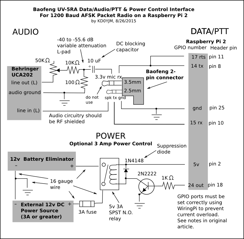
(Click schematic to enlarge)
(This article is intended for licensed AmateurRadio operators. If you are not a ham, and you enjoy reading articles like this, then become one↗! Please note that I am not an audio or radio engineer and have created this circuit for my own use only, providing information about the project in the hopes it will be useful to others in some way. It might not be suitable for you, and I am not responsible for the correctness of the information and do not warrant it in any way. Since this article was first published, I've made some improvements to the schematic above which were added to my later TrillSat project.)
- Introduction
- The Analog Wilderness
- The Super Interface
- Careful Toggling of GPIO Ports
- Remote Operation
- The Data Interface
- The Audio Interface
- RF Concerns
- APRS
- SSTV
- Notes on Using a USB CM119 and Pi Zero W with Dire Wolf
- Testing With Dummy Loads
- Hardware
- Software
- More Ideas and Hindsight
- Conclusion
Introduction
I am relatively new to Amateur Radio and received my Technician class license in 2013 and my General in 2016. My Elmer gave me my first radio in 2014, a 2-meter HT, the Baofeng UV-5RA, but I hadn't actually tried transmitting until a year later. He also showed me an AX.25 packet radio communication across the woodsy hills of Union, Missouri, the first time I had ever seen one. I had read about packet radio in the late 1980's, and by the 1990's I was thinking about getting a ham license to use them, but then I discovered the Internet and forgot all about it.
In the early 1990's, I began connecting to the Internet using an Amiga 500 computer and a Commodore64 1200 baud modem, using an interface I had constructed. I was only using a terminal to connect to a more powerful mainframe shell, but once I FTP'd files to my account on the mainframe, I could then transfer them from the mainframe over the slow 1200 baud link to my Amiga via the Kermit protocol.
Packet radio (the 1200 baud variety) uses Bell 202↗ AFSK (Audio Frequency-Shift Keying) tones, very similar to the Bell 103/212A tones that my old Commodore 64 modem used, but even that C64 modem switched to a more advanced PSK (Phase-Shift Keying) mode instead of AFSK for 1200 baud. So by modern standards, AFSK technology is archaic. In fact, hams were using it even before my eighties teenage self. Similarly, in the 1970's, a protocol called X.25 was invented, a packet protocol that predates the IP protocol used by the Internet, and predates the OSI model↗ that IT network technicians know well. Most of the world now uses TCP/IP in place of X.25, but hams still use the old AX.25, a protocol based on the older X.25.
So it is eerie for me to hear those old modem tones over some of the ham radio packet frequencies. I haven't peeked behind the veil of ham radio long, as I am learning its history from this day backwards, or top-down; I didn't live the history. Supposedly, there was a heyday of packet in the 1990's when I was a young microcomputer fanboy, but like Unix (which took me years to decode), it was a world that I never saw. I asked an Extra Class ham at the local electronics store the other day about packet and he said he hadn't used packet in decades.
Packet is no longer cool, I guess. I've read that PSK31↗ is one of the cool new digital modes, and I tried to decode PSK31 using a soundcard and shortwave radio a few weeks before I encountered packet on VHF, and it failed miserably. I couldn't find a strong, low-noise PSK31 signal, so all I received was phase-shifted gibberish. But yes, it is very cool for what it does, and one day I will use a better antenna and find a strong signal.
But as for today, I'm experimenting with AFSK↗.
One of the things about communication technologies is that coolness actually does matter, because the purpose of the technology is to communicate, and if you have nobody willing to use that technology, then you have nobody to communicate with, not even a lonely machine. I have built several communication systems in my life, and the stark reality is that sometimes your system is all dressed up with nowhere to go.
There is also the idea of efficiency. A radio communication can be efficient in terms of space (spectrum use), time, or energy (total power). Some modes are more efficient for different modulation techniques (amplitude, frequency, phase), for different frequencies, for different distances, and even the characteristics of the information that is being communicated. This is analogous to data algorithms and protocols in the computer world; each new method is simply a trade-off between fixed resources, an optimization problem. Communication is also mysteriously intertwined with the quantum world, information theory, and entropy...
So when I returned to St. Louis and fired up that tiny Baofeng late one night in August 2015, hearing the periodic data bursts of a single station within range of my tiny antenna and crude interface, seeing the first words appear on the screen, it was like the Hedgehog discovering the White Horse↗. I had crossed the veil.
It turns out there is one 1200-baud digipeater within reach of me that happens to be part of a backbone that an organization in my state of Missouri is trying to expand to span all the major and second-tier cities, primarily for emergency use. But as of this writing in 2015, they have opened it up for general amateur radio use which is fortunate for me, as it allows me to access otherwise unreachable nodes.
That 1200-baud data rate seems slow, but the beautiful pictures of Pluto and Charon that we first began seeing from the NASA New Horizons spacecraft in 2015 were sent to us over several months at around the same data rate using BPSK modulation over a 12 watt transmitter. Compared to the power density of that signal over 3 billion miles, a 5 watt Baofeng is a titan.
I sent a store-and-forward message using a PBBS↗ to my Elmer and it was routed node-to-node and he received it. No Internet or cell towers needed. Packet radio is still here.
I'm not a socializer, I don't ragchew. I was the first in my group of peers to discover the BBS as a teenager in the 1980's, and the first to discover the Internet in the 1990's, and later Linux (downloading Slackware over a 14.4K modem). But while my peers took their newfound connectivity to voraciously e-mail, group-chat, instant message, IRC, and eventually social-network, I didn't. I wanted to talk to machines, not people.
I was a downloader, a leech, a lurker. I wanted pure, refined Knowledge from the Library of Alexandria. When the WWW formed, thanks to HTTP, I could now easily "download" HTML. It was one of the greatest gifts of knowledge that Mankind passed down to us, as an individual. Thank you, Sir Tim Berners-Lee, for making it so easy for me. I was just digging Gopher↗ out of its hiding places on my college mainframe and then wondered, what is this HTML you speak of?
Talking to machines can be a very fun thing. It is still human communication, but Time shifted, like the very words you are reading right now, which I wrote in the past. Actually, the more I think about it, it is more like "phase-shifted" human communication. Think about this--a human creates an algorithm to respond to another human in the future, but respond in a way that is suitable, determined by their algorithm, slightly "out of phase" with the original creator, like one of the myriad branches of the tree of the many-worlds. It is an adventure to uncover a hidden world behind cryptic text menus and parsers. Back in the BBS days, there were so many different types of BBS systems that you didn't exactly know how to navigate each one. They had different "personalities" and doors↗. I have had a fascination with vending machines and RogueLike games for most of my life; secret boxes that present you with Choice.
SHALL WE PLAY A GAME? _
It is not too difficult to create a roguelike, MUD, or InteractiveFiction style game that operates purely over packet radio. Those types of games can make very efficient use of short amounts of text (saving bandwidth). I recently programmed a similar game using Morse code, so it could even be done over CW. But the game can also be played via short ASCII text strings over the UART, and after porting that tiny engine to the more powerful ARM architecture for testing, including creating a "finite state machine" mode, it is now easily playable over packet and can support multiple games simultaneously.
I haven't heard about hams doing this sort of thing, and I'm not sure why. It doesn't seem to be in conflict with the "Basis and purpose" of Amateur Radio as defined by FCC Part 97.1, although there is a "seriousness" to ham radio that is pervasive. Perhaps it is the difference between the completely open nature of the Internet and the more regulated and self-policing nature (and much older history) of the airwaves. I programmed a telephone-based BBS system back in the 8-bit days, and on my later TrillSat project, I took the leap and programmed one over packet.
However, I'm still trying to understand the power of the sleeping giant at my feet. EMF is powerful and enigmatic; it is light, making up one of the four fundamental forces of the Universe.
One of the wonderful things about ham radio privileges is that hams can build much of their own radio equipment and put it into operation immediately. You don't have to get your radio licensed, because you, the operator, are licensed. As long as you and your station follow the FCC regulations, bandplans, etc, then All Systems Go!
The Analog Wilderness
When I found out that computer soundcards and the Linux kernel could replace TNC's entirely for some protocols, I figured I already had the equipment needed (a Behringer UCA202 external USB sound card) and decided to interface the Baofeng to my RaspberryPi 2 computer. I have a long history working with digital logic electronics (5v TTL, CMOS, 3.3v TTL), and have used the Raspberry Pi series extensively for several projects since it was first released, but analog signal electronics (especially RF) is in an entirely different class and is outside of the realm of logic/discrete math and into the oscillating world of Algebra and calculus. I studied the history of radio/television in college, and watched Ken Burn's Empire of the Air back in 1992, both of which made me acutely aware that early radio inventors had a strong background in higher mathematics. The very equations that united electricity and magnetism (that we all call electromagnetism) were discovered by a Scottish mathematical physicist named James Clerk Maxwell, expressed using differential equations. Differential equations are a "derivative" of calculus, no pun intended.
I don't think like a research scientist, I think like an armchair one. I dislike data gathering, stepping out of that armchair. I don't want to look for new weird stuff, I want to find out what that collection of weird stuff that we already have means, which I believe will contain the answers to our questions (which might just be a collection of new weird stuff). I considered myself a logician, and so I went into the discrete logic world of computers, not the wild, untamed physical world.
When I was a teenager, I went out of my digital comfort zone and tried to build a couple of tiny, low power FM transmitters, but they were utter failures. In fact the only circuits that I have ever built that I could not get to work were FM transmitters. All I had was a digital multimeter. I could only see the quanta, the DC, not the wave, the AC.
With digital electronics, the complexity comes from the number of modules and the switching and logical rules within and between them, and quite large circuits can be built from simple rules. This is how digital computers are constructed, which can then simulate additional complexity virtually, via higher-ordinate software abstractions. But with analog electronics, the complexity is in the subtle balancing of components; just a minor change to one component's properties can affect the whole system, since many of the electrical variables are interdependent and exhibit and encounter physical phenomena that is negligible or suppressed in the digital world. Working with just a tiny analog circuit can be more complex than a large digital one due to this dynamic nature.
Variable resistors, variable capacitors, and sometimes variable inductors are seen throughout analog circuitry, but are rarely seen in digital circuitry. This is because balancing those real world analog signals using pure logic (or even mathematics) is difficult to impossible to do, as each component has some amount of tolerance. There is a lot of Dieselpunkish↗ tuning and tweaking, and even Chaos can reveal itself here↗. Ironically, the digital computer can simulate the effects of various tolerances via software, but it is still a complicated thing.
Computers are easy. Radio is hard.
![]()
The digital and analog worlds seem to be two different worlds, but modern technology is causing us to acknowledge that they are the same, creating a bridge between worlds, forcing me to step out of my armchair and into the wilderness. There was an interesting 2014 Japanese anime film called Expelled from Paradise↗ that depicts this sort of fall from a virtual world.
The Baofeng performs signal processing using the RDA1846 signal processing chip, which is a custom microcontroller using an integrated DSP, almost like software-defined radio. This is in my comfort zone, as I spent a lot of time programming a microcontroller using a Raspberry Pi, and learned some techniques to creatively use GPIO lines to simplify external circuits. I am good at switching circuitry, and so I build systems that switch, switching systems in and out to solve problems.
A lot of people have interfaced this series of radio into computers, but because this device is both a computer and a radio, most people use it in two very different modes, and use two very different interfaces, the digital programming mode and the analog transceiver mode. But by combining these two modes into a single, consolidate interface that is toggled via software, the setup can become a very useful remotely-controlled packet station, which I will discuss later.
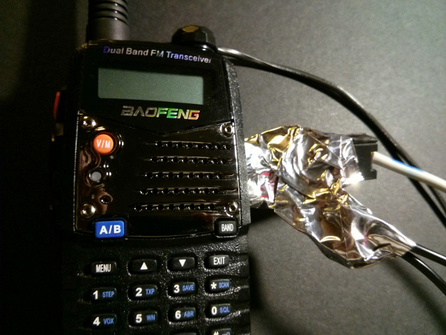
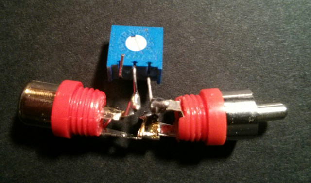
The Super Interface
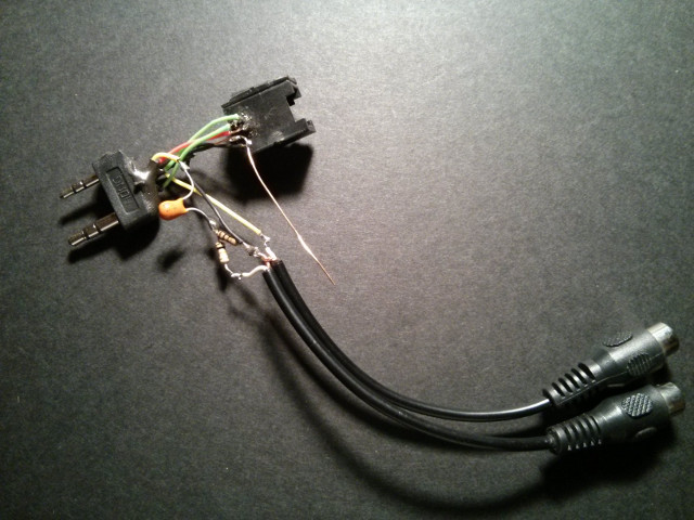
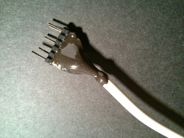
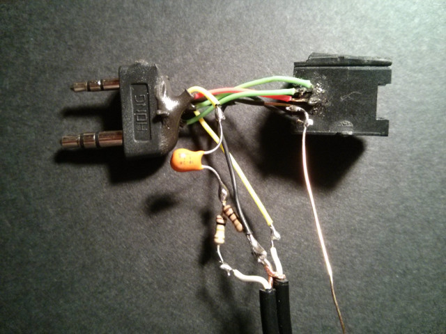
It doesn't look like much, but it does a lot. It eliminates the need for a typical a USB programming cable (which contains a built-in USB-to-serial adapter), and it also allows audio in/out and Push-to-Talk (PTT) so that the function of a TNC can be done in software.
The 2-pin connector, which some people have documented in a detailed new manual 1.0 for this series of radio, combines those data lines and audio/PTT lines. The manual does not show the data line connections, which makes it a little confusing. Also, on my UV-5RA, I measured 3.3 volts, not 5 volts, as the manual shows. Someone has created a schematic for the UV-5R series, which can be found online, also showing 3.3 volts, which I assume is intended for external mic power.
A lot of hams have created complex interfaces to connect the data lines to traditional RS-232 ports, interface USB-to-serial chips, and use ground loop isolators and VOX to prevent Push-To-Talk from auto-activating, but all of this is unnecessary if you use a Raspberry Pi. I already had a Raspberry Pi 2 and an audio capture device, so the total parts cost for me was less than $1. I cut up an old RCA-style phono Y-adapter to obtain shielded female phono jacks and cut up the headset/mic that came with my radio to obtain the connectors (plugs) that I needed. The included headset/mic is not wired to all of the 3.5 mm and 2.5 mm TRS phone connector pins, so I had to cut open the 2-pin connector itself to get access to them.
Careful Toggling of GPIO Ports
The key is to be careful to set the ports in a certain order to switch between the different circuits, while preventing damage to the Raspberry Pi 2, since full output highs or shorts to ground without current limiting resistors can overload its GPIO, and you don't want to accidentally activate PTT. So while this is a fairly simple interface, it is simple since it lacks hardware-level protection.
The Raspberry Pi 2 sets its GPIO ports to a default state on boot, which can be viewed right after boot by typing "gpio readall" using the WiringPi↗ software, showing the mode and voltage (high/low or 1/0) status of the BCM port.
The Pi's TX line is connected to the Baofeng's RX line for programming, but if the Baofeng RX line goes low (ground), it will activate the PTT. Luckily, the Pi's UART lines are enabled by default and held to a logic high (1) when idle, which is standard for UART signaling. If a spontaneous reboot were to occur, the TX/RX lines might briefly go from low before reaching their high default state, but this does not seem to trigger PTT because the pulldown is such high impedance that it doesn't activate PTT or the transition is too fast for Baofeng PTT detection (probably the former).
For some reason, and good for this circuit, the lower impedance UART signaling also does not activate PTT, as the radio seems to ignore it during the data transmission. Perhaps it is too fast for the PTT detection to activate, or the radio senses a data transmission and turns off the PTT detection, I don't know.
I used Thomas Sailer's Soundmodem↗ Version 0.18 as the software modem on this project along with MKISS (but in my later project I switched to headless Dire Wolf and KISS pseudoterminals). The AX.25 protocol is built into the Linux kernel. I set Soundmodem to use the /dev/ttyAMA0 serial port of Arch Linux ARM for the PTT Driver, the ALSA Audio driver of plughw:1,0, Left capture channel, and MKISS interface of SM0. Soundmodem can activate the radio's PTT mode by setting the serial port's RTS line to low, of which I took advantage in the circuit.
I also set Chirp to use Port /dev/ttyAMA0 for programming.
Finally, I had to remove all references to /dev/ttyAMA0 from the /boot/cmdline.txt file in Arch ARM, and make sure getty@ttyAMA0 was disabled in systemd to prevent the OS from using the serial port for its own purposes.
The htpacket and htchirp commands
For good measure, I keep the radio turned off if I just turned on the Pi until I can first confirm the status of the GPIO ports using "gpio readall". This should definitely be checked after software updates, since it is possible that software changes could alter the defaults after boot.
I created aliases in my .bashrc script called "htchirp" and "htpacket" which run the relevant GPIO commands (note that this won't work on a Pi 3 or Pi Zero W without configuration changes, as their default UARTs are set differently--see this section at the end of this article for more information).
alias htpacket='gpio -g mode 14 input;gpio -g mode 17 alt3'
alias htchirp='gpio -g mode 17 input;gpio -g mode 14 alt0'
Then I just type in the alias anytime I switch modes. For example:
To read or program the radio's memory using Chirp
First I run htchirp, then I can turn the radio on and launch Chirp via chirpw.
To use packet radio
First, I use CTRL-C to make sure Soundmodem is stopped. Then, I run htpacket. Then I launch Soundmodem and wait a few seconds in case it tries to transmit on startup. Now I can turn the radio on and use "listen -a" to monitor a frequency or use the call command to transmit.
Explanation
Once the radio is on, I don't have to turn it off again as long as I remember to use the aliases beforehand. However, I do have to stop and restart Soundmodem before typing "htpacket" because a previous "htchirp" command will have disabled the RTS line, removing control from Soundmodem. When the RTS line is re-enabled, Soundmodem can't seem to regain control over it, so it needs to be stopped and re-started. If this is not done, running htpacket can suddenly activate PTT, since the RTS line can go low if Soundmodem can't control it to keep it high when not transmitting. I suppose I could have added the commands to stop and restart Soundmodem to the htpacket alias, but I wanted to keep these functions separate.
I connected the RTS and TX lines together so that Soundmodem can pull the TX line low, which pulls the Baofeng RX line low to activate PTT. Ideally, I would not even need an RTS line, since TX can be configured to go low by itself, but Soundmodem 0.18 does not support triggering the TX line for this purpose.
If I am programming with Chirp, I must first disable RTS and set it to high impedance (input) to keep this line from interfering with the Baofeng RX line used by Chirp, otherwise it would go low when sending data to the radio, bringing the UART TX line low, interrupting the data transfer and triggering PTT. The RTS line, when disabled by setting to input, has a default 50K ohm pulldown resistor and will also drop low, but it seems to be at so high of an impedance that it does not pull RX low. Then I enable the UART TX line which is also used by Chirp. UARTs are kept at logic high when idle, so this will then pull the disabled RTS line high which keeps the Baofeng RX line high, and the PTT is not activated.
If I am using the transceiver for packet radio, I do the reverse and disable UART TX and set it to high impedance, then enable RTS. This allows Soundmodem to toggle RTS to pull Baofeng RX low to control PTT. The TX line also has a pulldown resistor, but RTS should stay high when idle, keeping TX high, unless Soundmodem doesn't have control over it, as mentioned above. Soundmodem will only pull RTS low when transmitting. If you don't disable the UART TX, it will keep the line high and not allow the RTS line to go low and activate PTT.
Again, when running the aliases, there is a fraction of a second between the 2 gpio commands before they fully transition, where the TX and RTS lines are both set to inputs with pulldown resistor (0). This does not set off PTT.
Caution!
There are two mistakes that can accidentally activate PTT and key the transmitter:
- If I forget to run "htchirp" before programming in Chirp, and it is still in htpacket mode. Chirp then performs a serial data transmission which toggles the RTS line (if it exists) which sets off the PTT. It seems that RTS stays low longer than TX/RX lines.
- If I forget to stop and restart Soundmodem before running "hpacket", if it is still in htchirp mode, which hangs the RTS line and it goes low, activating PTT.
A less serious mistake is to forget to type "htpacket" before transmitting via packet and it is still in htchirp mode. In this case, Soundmodem cannot activate PTT and I'll hear the noise but the transmitter won't turn on.
The Raspberry Pi 2 can be damaged if one were to manually set the pins to other states using WiringPi commands, such as an output high/low, possibly causing a short which exceeds the max current, since these two lines are directly connected.
Remote Operation
Since I don't like leaving my armchair much, and because I have worked in IT system administration for 30 years, I am used to being telepresent↗, sometimes several layers and systems deep. While first writing this article, I had my radio in another room, since I didn't want to have to walk back and forth. And since packet is text, and Linux loves text↗, this kind of stuff is ideal.
Because the radio can now both be programmed and act as a TNC via pure computer control, it can be remotely-operated over an encrypted IP network control link (via SSH keys, for example) by the control operator. The control operator and station could be co-located, with the operator in one room and the station in another, via a local area network, or a link could be created over the Internet for true remote operation.
The Raspberry Pi 2, UCA202, and UV-5RA are small, solid state devices that can be easily moved to another location, such as near a window, or at a high elevation. As long as there is a sufficient power source (or even solar power), the station would not need much maintenance.
However, under the FCC, the control operator must take steps to ensure that compliance is kept at all times. The station has to have some way of being shut down if the control link were to fail, so if the station is not co-located (at the same site) and you can't get to it quickly, then some sort of failsafe or killswitch mechanism should be in place to handle such an event.
Power Control (hton, htoff)
Aliases could be created in the .bashrc file to turn the radio power on and off:
alias hton='gpio -g mode 24 output;gpio -g write 24 1;'
alias htoff='gpio -g mode 24 output;gpio -g write 24 0;'
These are more WiringPi commands that simply set the GPIO port to output mode and then send a logic 1 or 0 to the port, which turns the 2N2222 transistor on or off, which turns the relay on or off, which turns a 12v UV-5RA battery eliminator on or off, which finally turns the Baofeng radio on or off (assuming the radio's power knob is already turned on).
I have not constructed or tested this circuit for use with the Baofeng (since at the time that I first wrote this article, I had no need, since my radio was co-located and I am present at the same location), but I have used this relay circuit for switching other devices on the Raspberry Pi series, and it works well for me.
I am already using GPIO 24 for the reset line of my AVR programmer, so it is conveniently exposed, and I don't have to open the case and connect any more jumper wires. The default state of GPIO 24 is 0, or off, since it is set to high impedance input and has a pulldown resistor, so the radio should not power up at boot.
To build the power control interface, I would cut off the 12v car adapter plug of the battery eliminator and wire it accordingly. There are different brands of battery eliminators available, some with switching regulators, some with linear regulators. The UV-5RA manual that came with the unit states that the radio draws 1.4 amps or less when transmitting. A 90% efficiency switching regulator might require under 2 Amps, but a linear regulator could exceed 2 Amps, so I designed the circuit to handle 3 Amps to be on the safe side.
Later note: For my newer TrillSat project, however, I created a solid-state version of this power control circuit, replaced the NPN 2N2222 with an NPN 2N3904 (along with a 10K pullup resistor to supply voltage connected to the collector), and replaced the relay with the gate of a P-Channel FQP27P06 logic-level MOSFET. I have tested this combination with the Baofeng UV-5RA, and it does work reliably enough for me. The battery eliminator can still be used, of course, but in the TrillSat project, I did not have 12 volts available and instead connected two parallel sets of nominal 3.6 volt Panasonic Lithium ion NCR18650B cells in series, producing nominal 7.2 volts, which I connected directly to the Baofeng battery terminals. In some cases, when I only had 3.6 volts available, I also used a 5 Amp switching LM2587S-ADJ DC-DC boost converter board to boost a parallel set of the 3.6 volt cells to 7.4 volts, which will also power up the Baofeng (it isn't as preferable, however, due to potential for RF noise/DC ripple). On the left side of the TrillSat schematic, under "Circuit Board A", you can see my new power control circuit.
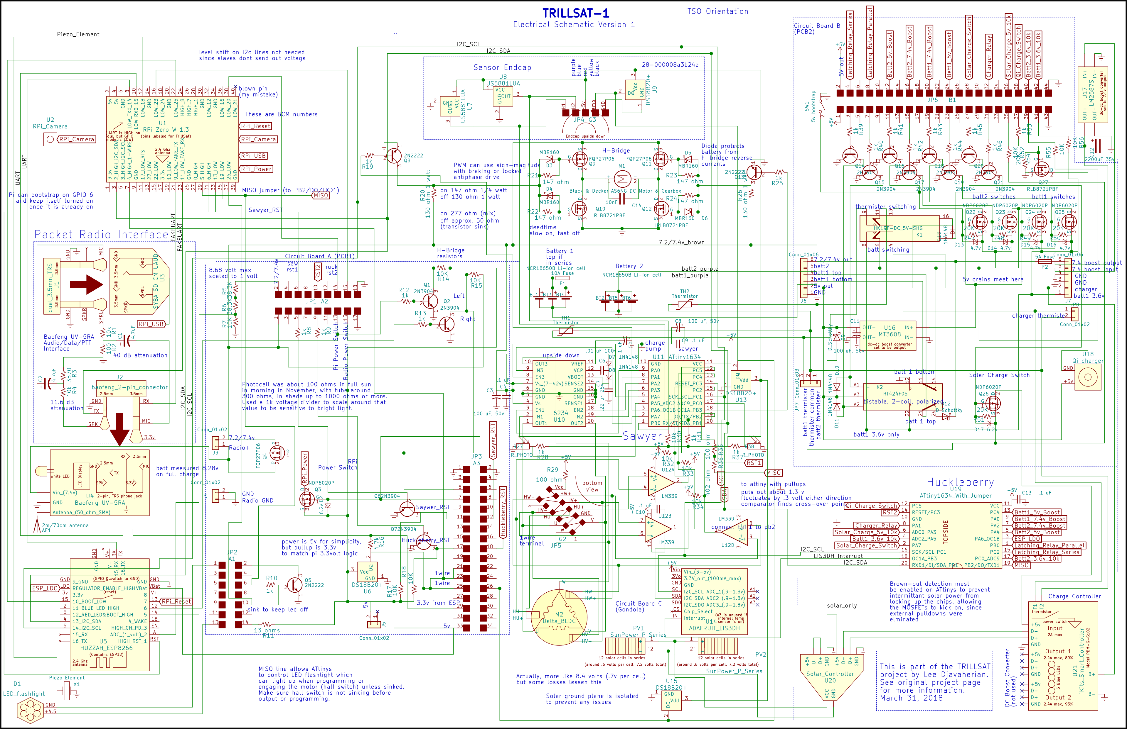
Transceiver Control
To remotely change the radio's frequencies, bandwidths, or power levels, Chirp can be run over X Window forwarding using "ssh -X" . The Chirp software can change the "work mode" settings, which allows you to change the frequency on the VFO by reprogramming, and then the radio will reboot and start on the new frequency. It is slow, but it works. However, in my later project, I created a faster method of changing the frequency by writing a 16-byte chunk of flash memory (which includes the 8-byte VFO work mode frequency) directly to the radio without the need to use any Chirp software, which is much faster and creates less wear, since it doesn't write to the entire flash. It also works headless, without the need for X-windows or a GUI. The process can be adapted to other settings besides frequency, but is too complex to describe here--please see the TrillSat project and its source code for more details.
This setup also opens up the possibility for remote control of a packet digipeater or PBBS running on the Raspberry Pi 2. Note that this would be considered "automatic operation" and must be in compliance with the FCC.
Failsafes
- Creating a keepalive signal over the control link will allow the server to power down the radio if the control link goes down (see example scripts below).
- The radio's TOT timer can be set in the menu to shut off transmission after a certain number of seconds (for example, 180 seconds for 3 minutes).
- Using a normally open (N.O) relay will ensure that a loss of power, malfunctioning transistor, or Raspberry Pi reboot will keep the power supply disconnected from the battery eliminator.
- Using a fuse at the power source is also a good precaution, especially if higher circuit current is involved.
- Arch Linux systemd can be configured to auto restart processes if they fail.
- The Raspberry Pi's CPU has a hardware-based watchdog timer than can also be enabled to reboot the computer if a kernel failure occurs.
- It is important to choose GPIO ports with default states that don't activate the transmitter or damage the circuitry on reboot, since the default states vary depending on port. These states should be verified after every software update using "gpio readall" just to be sure that new software doesn't alter the state.
Example Failsafe Scripts
A simple series of commands in a BASH script could be added to CRON running on the Pi to connect via SSH and create an empty file on one of the server's ramdisk tmpfs directories once every minute, and the server could be similarly programmed to poll and delete the file once every minute, perhaps using NTP for accurate timing. If the server doesn't find the file during one of its polling attempts, it shuts off power to the radio completely, acting as a killswitch↗. This mechanism should stop a transmission within the FCC Part 97.213(b) 3-minute limit if the control link malfunctioned. It is also independent of the control link (the server simply looks for the existence of a local file). If timing is exact, the server will poll itself faster than the client can create the file, but if the server is a few seconds slow, it will still catch it on the next round, so it should cut off transmission in 2 minutes or less.
The example scripts below take advantage of the /tmp folder on Arch Linux which is mounted as tmpfs (ramdisk) on boot to prevent excessive writes to the flash storage, and they also assume that ssh keys are setup between client and server using an ssh config file to simplify the ssh command string (which can get rather long with username, port, keyfile, etc). These are just example scripts, and I have not tested them.
Add CRON entry to client:
*/1 * * * * /usr/bin/ssh my_server_name 'touch /tmp/control_link_active'
Create script called "check_control_link.sh" on server:
#!/bin/bash
if [ -f /tmp/control_link_active ]; then
  rm /tmp/control_link_active
else
  gpio -g mode 24 output
  gpio -g write 24 0
fi
Then add CRON entry to server:
*/1 * * * * /bin/bash /check_control_link.sh
The Data Interface
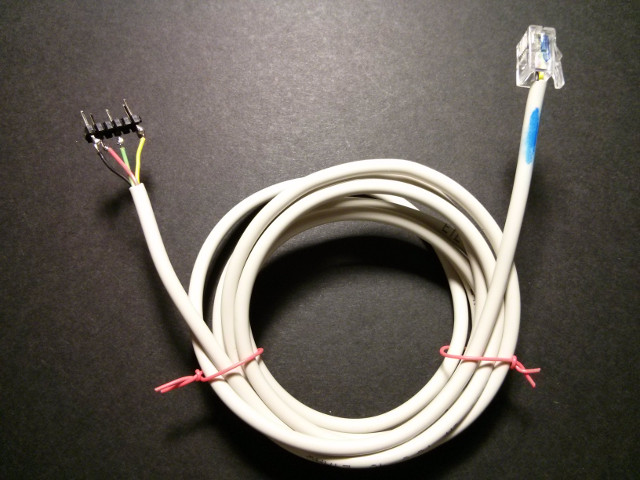
The Baofeng radio has 3.3v UART TX/RX data lines on its 2-pin jack which can be connected directly to the 3.3v UART of the Raspberry Pi 2. The latest daily build of Chirp↗ can then program the radio. I was not able to communicate with the radio using the stable 0.4.1 version.
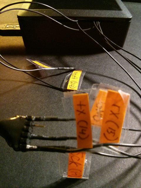
I connected an RJ-11 jack to these lines and ground, then used 5 feet of unshielded, 4-conductor telephone wire and soldered a set of jumper pins to the end. I made it long enough to match the length of the audio cables I used so that I could set the radio up high on a shelf and move the bulk of the Baofeng's RF energy away from the Raspberry Pi and UCA202. I then covered them in epoxy to strengthen. The data speeds are low so this is good enough for me.
I prefer interfacing into the Pi's GPIO using tiny jumper cables instead of large ribbons and connectors, because it gives me more flexibility. I had already exposed 6 lines for SPI programming of an AVR microcontroller using Avrdude, and so I was conveniently able to use those same lines for the Baofeng. For example, when programming the AVR, I set Avrdude to use GPIO port 17 for SCK, but when connecting to the Baofeng, I use WiringPi to set it to RTS mode so Soundmodem can use port 17 for RTS.
The Audio Interface
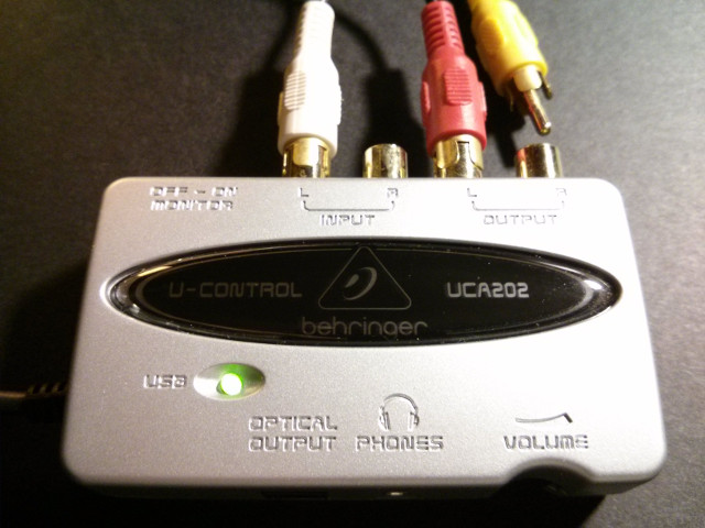
The Raspberry Pi 2 has no audio input, so you have to connect an external sound card. I used the left channels of a Behringer UCA202 USB DAC with line-level input/output, since it was all I had. I didn't have good results with a cheaper USB soundcard, but the TI PCM2902 audio chip of the UCA202 is satisfactory, and a lot of audiophiles and some hams have written technical articles about the UCA202. It has no internal mixer, like most other sound cards, however, so you can't adjust the hardware volume. I suppose a software mixer could be added via ALSA Softvol, but I haven't tried it.
For my newer TrillSat project, however, I was also able to create a similar circuit that worked successfully with the smaller and less expensive SYBA SD-CM-UAUD USB Stereo Sound Adapter which used the CM119 chip. See this section for more information.
The radio doesn't have line-level audio connectors, so I had to convert them.
The 2-pin stereo connector used by the Baofeng is not too common, and is often referred to as a 2-pin Kenwood-style connector. Since I couldn't find one locally, I decided to cut off the headset's 2-pin connector, but I found that it did not use all of the 6 conductors on the plugs. So I cut open the plastic connector with wire cutters and chipped out the dark-grey, epoxy-like substance and removed the 2.5mm and 3.5mm TRS (stereo) pins. I was then able to solder wires directly to the terminals of the pins and carefully re-align and epoxy them back into the connector housing, which I was careful not to destroy.
Impedance Bridging
Since I had essentially destroyed the headset, I decided to remove the mic and the earphone speaker to measure the DC resistance with a multimeter. The earphone was just around 32 ohms, and the mic measured around 1K ohm one direction and 1.3 K ohm the other. I opened the mic capsule and found what appears to be a tiny FET pre-amp of an electret mic. I have no idea what the actual impedance would be when the transistor is powered on.
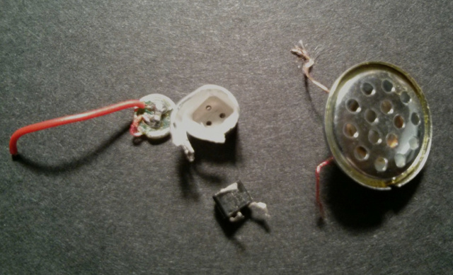
The 32-ohm earphone impedance seems to agree with the RDA1846 datasheet, which can be found online, which shows a 32 ohm direct resistance loading of the internal Digital-to-Analog converter. In other words, the DAC appears to be driving the earphone directly, without the need for an additional amplifier.
Similarly, the mic is wired directly into the Analog-to-Digital converter (ADC) of that chip. The mic impedance, however, does not seem to be listed on the datasheet, so I will assume that it is 1K ohm, which is common for electret mics. However, the schematic shows a 6.8K resistor in series with the mic-in line on the RDA1846 chip, so perhaps the actual impedance to the ADC is closer to 8K ohm.
According to the UCA202 manual, also available online, the line out impedance is approximately 400 ohms, and the input approximately 27K ohms.
I am not an audio engineer, and so at first, I tried to impedance-match the line-out signal of the Behringer to the Baofeng mic, but I later read that audio electronics do not use impedance-matching for things like this.
This was strange to me, as I was taught about the importance of impedance matching for RF antenna tuning, and the load impedance (the mic) is much larger than the source (the line out jack).
But, from what I've read, with these kinds of signals, you perform impedance bridging↗, transferring Voltage efficiently, not Power (which is Voltaqe x Current). I guess reflection is not a big problem at those power levels. Some people refer to this as "voltage matching". In the old telephone days, it seems that they used more coupling transformers, but modern electronics seem to use more resistors (direct coupling).
A line out is considered a fixed source level, and so you simply match that impedance, and then pick a load impedance as "high as possible", but not "too high".
Connecting the 32-ohm earphone line (source) of the Baofeng to the 27 K ohm line-input (load) on the UCA202 is well-suited. Line-level voltages are low (under 2 volts) and earphone voltages are not too much higher, so you can just adjust the volume level until it sounds good with no distortion or clipping. This isn't as critical as the Baofeng mic level, since it is not transmitted on the airwaves, as I'll mention later. It isn't perfect, but it seems to work without additional circuitry.
Well, electret mic-level amplitudes are much, much lower. I looked up the mic sensitivity of typical 1K ohm electret mics that were being sold online, and many of them had a sensitivity of -44 to -45 dB/Pa. From my understanding, this value was derived from a 1 Khz sine wave at 94 dB SPL.
The UCA202 manual uses the -10 dBV as a reference for THD, so I also assume it is a consumer line level device. This is convenient, since consumer line level uses the same 1 volt reference that the mic sensitivity uses, so to get -10 dB level to drop to -45 dB level, if my mic was the same as the mic I found online, I would need a -35 dB attenuation. Note that the decibel values for Power and Voltage are different, which I thankfully learned from my class instructor. I am therefore using the voltage version.
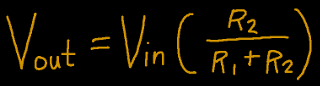
I decided to use an attenuator circuit called an L-pad, a type of passive, resistive voltage divider↗.
Now here is where it gets complicated for a ham newbie like me...
When you attenuate an audio signal for listening purposes, it is easy; you just adjust the volume to a nice level were it doesn't clip and it is not too low.
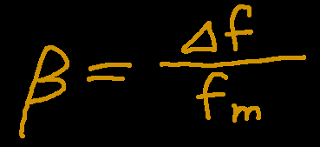
But when you send out an audio signal to be modulated and transmitted for FM, the volume of the audio also increases frequency deviation which changes the number of sidebands, increasing bandwidth. But increasing bandwidth does not necessarily lead to a more intelligible "data" transmission, especially with fairly simple, two interchanging tones of 1200 Hz and 2200 Hz.
I decided to create a typical L-pad with a -40 dB "amplitude" loss (100x). It would provide a weaker signal than the -35 dB derived from sensitivity reference, but I can't confirm that my mic was the same as the mic I found online, and I didn't want to overdeviate. A -40 dB loss is also typical for line-to-mic L-pads. I assume that the radio was designed to handle softer and louder sounds than the reference (if someone was whispering or shouting, for example).
It is more power efficient to reduce my bandwidth to only the minimum needed to convey information. If I were to pump too large of an amplitude into the Baofeng mic input, it could cause the RF transmission to deviate from carrier so far that it would go outside of my 20 Khz channel spacing and interfere with neighboring frequencies. I chose Narrowband mode on the Baofeng which I assume has some sort of audio compressor to limit levels to keep it from producing an RF deviation that would exceed 12.5 Khz bandwidth, but even so, I don't want to push up against this. If I used Wideband mode, the radio's compressor might allow a signal to expand to 25 Khz bandwidth, which would allow a highly-deviated signal to overlap 2.5 Khz onto each of the adjacent channels.
I chose an L-pad with a 10 K ohm series resistor (R1) and used a 100 ohm shunt resistor (R2) for the 100x or -40 dB loss. Line outputs are designed to drive 10 K ohm inputs (or higher) so this was easy, and I was very familiar with the voltage divider equation (shown above) from powering digital circuitry.
AC Coupling
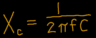
I inserted an AC coupling capacitor↗ which blocks any DC over the mic jack. It hums if I don't use it. But blocking capacitors have to be properly chosen as well, as capacitive reactance and high-pass filtering occurs with alternating current circuits.
I chose a 10 uF tantalum capacitor, which is polarized. It doesn't need to be polarized, but that was all I had. Some people say that tantalum capacitors add distortion to the audio, but at mic-level amplitudes, the signal is so small that I assume distortion to be small enough for this purpose.
The radio needs to clearly receive 1200 Hz and 2200 Hz tones to represent the binary 1 and 0.
There is a capacitive reactance formula that gives the relationship between reactance, frequency, and capacitance.
The smaller the capacitor, the higher the reactance at low frequencies. In other words, at low audio frequencies, if the capacitor is too small, the reactance will start to increase the impedance, and the volume level will drop off at lower frequencies, acting as a high-pass filter. In fact, this is how some speaker crossovers work. My father used to use crossover capacitors for the quadraphonic↗ speakers that he built inside wooden barrels in his 1970's discotheque, so I was somewhat familiar with them.
For 1200-baud packet, this is only a problem if those low frequencies are higher than 1200 Hz and if the attenuation is so high that the volume is too low to be heard by the Soundmodem software decoder.
I placed the AC coupling capacitor on the mic level side since the voltage is lower and capacitor signal distortion is generally said to increase with voltage levels. It also has the benefit that when reactance occurs, it raises the impedance of the mic input. If I were to instead put the capacitor on the line level side, it would have changed the value of the voltage divider and attenuated the amplitude, but on the mic side, it turns the L-Pad into a T-Pad and starts to add to the 100 ohm mic impedance (load), increasing toward the 8K ohm actual mic impedance.
It is interesting that if it reached somewhere around 8K (or whatever the actual impedance of the mic) somewhere around 2 Hz, there would be a load impedance match, optimizing power transfer, according to the maximum power transfer theorem↗. I believe this is called a "complex conjugate match", but I'm not certain. However, since this is audio, I don't care about power transfer, but voltage matching. So reactance seems to have a negative effect, except for the fact that it attenuates the amplitude (and therefore the noise) that occurs below the lowest Bell 202 1200 Hz tone. Perhaps an even smaller capacitor would reduce even more noise, but I wanted my setup to also work for voice frequencies in case I wanted to use other modes.
Again, I am not an audio engineer, and I do not have an oscilloscope, so I am just doing a thought experiment here. It is extremely difficult to visualize analog AC signals without having an oscilloscope, and you can't see the "actual" real-world values. So I have to rely on my best logical deduction.
The RDA1846 datasheet suggests to use 47 uF capacitors to couple the mic and speaker audio signal paths. I did some calculations, and at 1200 Hz, the reactance of a 47 uF capacitor is nice and low, at around 2.8 ohms. My 10 uF capacitor is around 13 ohms. Eh... still very low.
At 300 Hz, the low end of ham radio "voice frequency" (just above the sub-audible tones), capacitive reactance is 53 ohms. Even a voice signal should still get through the capacitor.
There are other dynamics like self-resonance, inductive reactance, and other effects at various frequencies, but I don't think they will be of concern in Bell 202 signals. It is mind-boggling how many interrelating variables there are in analog electronics, again, things that don't exist in discrete logic.
It should work for many other low-speed digital modes but not for 9600 baud, since the frequencies are outside of the audio range of the device, although some people are trying to get things like this working by disabling the filtering and emphasis circuits and interfacing to the radio circuitry directly.
RF Concerns
My channel spacing for packet radio in my area is 20 Khz. The Baofeng radio defines 2-meter wideband as 25 Khz bandwidth, 5 Khz deviation, and narrowband as 12.5 Khz bandwidth, 2.5 Khz deviation. But with FM modulation, bandwidth varies with amplitude and frequency, so I assume that these values are mainly just rough specs for the radio (how much amplitude its fixed gain mic puts out, how the compressor limits the audio signal, how much spectrum to demodulate, etc.)
I've never built a working FM radio, so I don't have a good intuitive feeling of the RF circuit. But I am fascinated with it, especially Edwin Howard Armstrong's superheterodyne↗ receiver. I'm sure that people who have succeeded in building such radios know exactly what the Baofeng and RDA Microelectronics engineers did with their circuit and DSP, but I have to logically bound these concepts without a good understanding. It is easy to learn something categorically, but you can spend your entire life studying that same thing and never understand all of its implications. Ideas are not defined solely by their denotation, but also in their connotative context within the Universe, and that is vast.
While working on this project, I read through a 1947 copy of F-M Simplified by Milton S. Kiver. This was published at the time Armstrong, the inventor of FM, was still alive. The famous transistor was invented that same year, so the information in that book is limited to vacuum tubes. However, I was surprised to find that most of the concepts that are discussed today about FM are in that book, including deviation, modulating index, sidebands, the capture effect, Bessel functions, pre-emph and de-emph, etc. The spectrum analyzer wasn't even invented yet, but the book contains sideband diagrams that look modern. They hadn't adopted the unit Hertz at that time and still used "cycles per second". FM broadcasting didn't gain popularity until later decades, but they understood the technology much better than myself. Kiver's book has time-shifted his voice 79 years into the future.
Books are cool.
So I was able to connect to my local station and send and receive packets, but it was hit or miss. One day it was fine, another day it was as if the remote station ignored me. So I upped the transmit power to its max of 4 watts and it seemed to work, but the next day it didn't. So I figured I had better further investigate my signal.
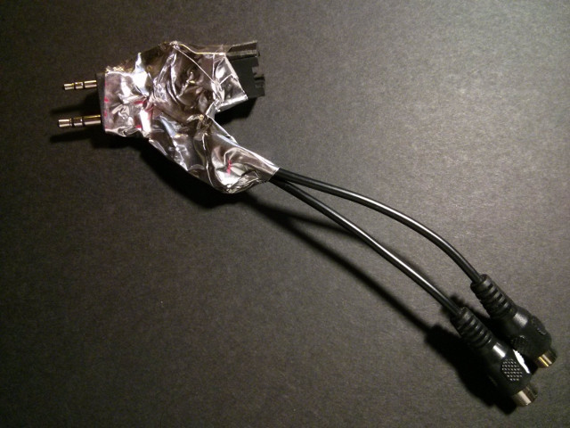
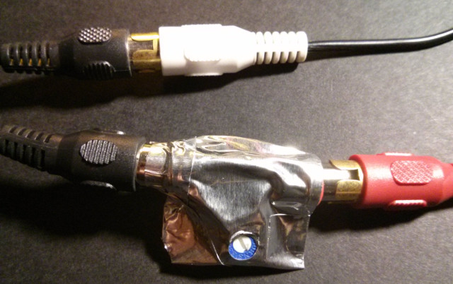
Shielding
At first I thought it was a distorted audio signal, possibly from RF feedback into the sensitive mic input, and so I insulated the inner wires with epoxy (to prevent accidental shorts, since they were too tiny for electrical tape), and then wrapped thick aluminum duct tape around the circuit and underneath a ground wire, then wrapped a top layer of 3M 1120 EMI shielding tape with conductive acrylic adhesive on top of the ground wire, sandwiching the wire between the 2 foils. The 1120 tape is more expensive, so I didn't use it except where I needed conductive adhesive. I figure if galvanic corrosion occurs over time, it won't affect the side that touches the adhesive, but I have no idea how long the adhesive will last. It's not the greatest, but it's better than no shield.
This reduced the max RF output of 4 watts of the included rubber duck antenna that was feeding into the sensitive mic-level input. It wasn't as critical to shield the 4-conductor data line to the GPIO on the Pi, since this isn't modulated on transmission, although it might be a good idea to shield it too or use twisted pair. Many Raspberry Pi cases (like mine) are plastic and unshielded, so keeping it far away from the transceiver is a good idea. RF power density drops off according to the Inverse Square Law↗, so every inch away from that antenna helps.
Since the shield is so close to the antenna (and rather large), I assume it is acting like a ground loss, so I tried rotating the unit but still had problems. Ideally, a properly tuned, external antenna should be used, which would also keep the radiation away from the interface, but I didn't have one at the time.
Counterpoise
I also added a 19.4 inch wire to the Baofeng antenna ground as a counterpoise↗ to give me a ground plane, since I am no longer holding the radio when used for packet communications. A quarter-wave antenna for 144.90 Mhz to 145.10 Mhz (common packet frequencies) would need to be about 19.4 inches, slightly shorter than 1/4 wavelength.
Using the SDR FFT Spectrum Analyzer
What suddenly occurred to me was that I could use my old SDR device as an RF spectrum analyzer! I had forgotten all about it, since I had previously just used it as a radio receiver. I fired up GQRX↗ on an RTL2832U SDR device↗ that I bought last year using a more powerful PC. It is a NooElec NESDR Mini 2 with an R820T2 tuner that is said to have greater sensitivity and SNR. It came with a little telescoping ground-plane antenna. It is not the correct length for 1/4 wave, 2-meter, but I suppose it could be adjusted to 1/8 wave.
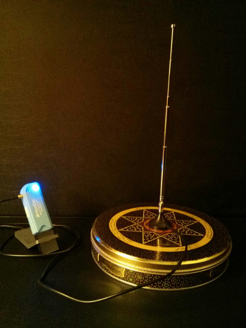
GQRX also has a software AFSK1200 decoder. So I left the decoder running and found that the RTL2832U with its crude antenna was receiving packet transmissions from the remote station that my Baofeng/Soundmodem setup could not. I turned off squelch on the Baofeng and it improved significantly. I assumed that either the included helical 1/4 wave rubber duck antenna on the Baofeng was not sensitive enough to produce a strong signal to noise, or Soundmodem was having trouble hearing the transmissions, so also I tried lowering the volume setting on the Baofeng, and it improved further. It might have been clipping.
Frequency Deviation
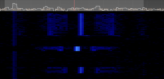
Well, I magnified the spectrogram of the narrowband frequency I was using, and when I compared the waterfall spectrogram of the remote station with mine, mine showed multiple sidebands spreading out to around 10 Khz bandwidth.
There is an equation called Carson's Rule, from John Renshaw Carson, the inventor of single sideband, another fascinating (and very efficient) modulation technique, which estimates the maximum bandwidth of an FM carrier:
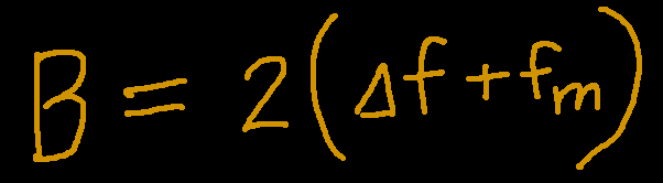
The max frequency of AFSK is 2.2 Khz. So if we have a deviation of 2.5 Khz for narrowband, the bandwidth needed for all of those sidebands is 9.4 Khz. This was approximately what I was seeing.
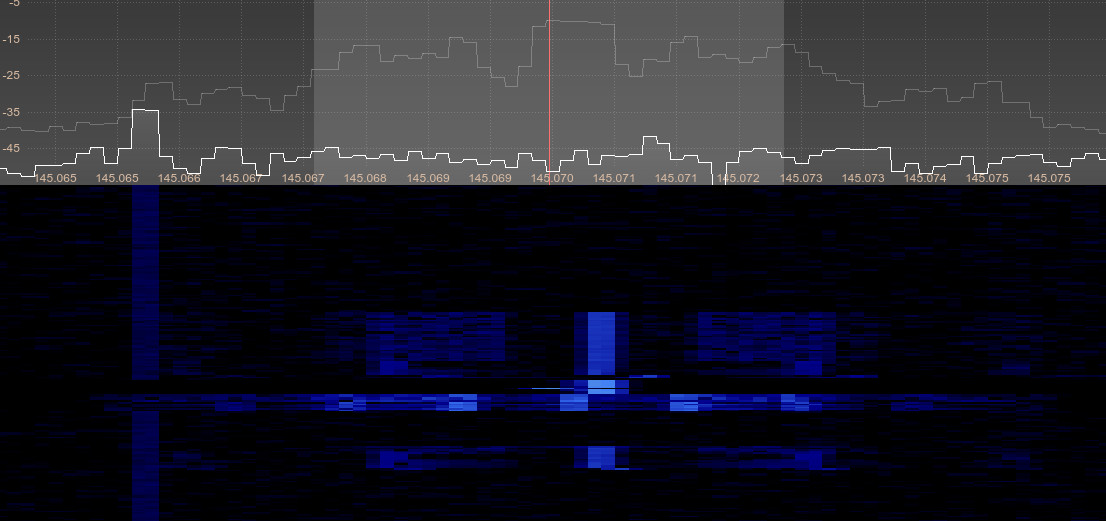
The really wide signal with the multiple sidebands is mine, in-between 2 bursts of the remote station, frequency offset slightly to the left. It has a weird overlap with the remote station when transmission ended. I think this was a sub-audible Squelch Tail Elimination tone that I forgot to turn off on the Baofeng, which might have collided with the remote station. Packet stations are simplex and designed to negotiate collisions.
I also noticed that the remote station frequency was about 500 Hz too high, and the Baofeng was better and closer to the actual frequency. I had earlier adjusted the GQRX frequency correction to 70 ppm, using some known signals in the area, since the NooElec oscillator had some error. Some people have said that this error drifts over time or when the device heats up, but I checked a couple of known signals in my area and they lined up at around 70 ppm.
Some of the reception problems are probably also due to this slight frequency offset between the remote station and my Baofeng. The UV-5RA can only be tuned in a minimum of 2.5 Khz steps for receive frequencies, but luckily you can set an offset of just a few hundred hertz in Chirp to shift your transmit frequency just slightly to match the recipient.
Adding More Attenuation
I was concerned that my signal was much wider than the remote station, so I decided to attenuate the signal further, adding an additional series resistor (a 50K potentiometer) to the line level output of the UCA202, and I adjusted it to 25K. This increased the L-Pad series resistance to 35K, creating an attenuation of around -50.9 dB.
Then I insulated and shielded it like I did on the original circuit.
Once I added the second series resistor, the sidebands were reduced and it looked very similar to the remote station signal. I turned off the Squelch Tail Elimination and the weird overlaps at the tail stopped.
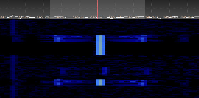
The reliability surprisingly improved, and 1 watt with this deviation was even better than 4 watts at the higher deviation. I'm not exactly sure why. Mine is the one with the bright blue carrier, shifted more to the left. There is probably too much energy wasted in my carrier, however. My signal now looks very similar to the remote station having only 2 sidebands.
I don't know what that strange vertical band to the left is. It might be a remnant of my NooElec oscillator or USB noise. Whatever it is, it is not from the Baofeng, and it is very low.
However, I later found out that Carson's Rule is an estimate for complex, multi-tone sounds. In the 9th Edition of The ARRL Extra Class License Manual, it explains that AFSK signals require much less bandwidth than complex sounds, based on work in Information Theory.
This is another point where the digital world and analog world collide. The fancy waves now metaphorically collapse under the pressure of the discrete world. When we impress our idea of information on a signal, it begins acting discretely to us.
You first obtain the change in modulated frequency or "shift" between the high and low tones, which is 2200 - 1200 = 1000, and then the "speed" or baud rate, in this case 1200 baud. The Bandwidth is then:
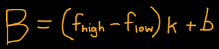
where k is a constant that is normally set to 1.2 for Amateur Radio, which is related to the shape of the keying envelope. So the bandwidth is (1.2 * 1000) + 1200 = 2.4 Khz, much less than Carson's Rule estimates.
Well, on the first spectrogram, I could barely make out two sidebands really close to the carrier, about 2.4 Khz bandwidth. So I started doing more research on proper deviation for FM narrowband packet.
There is a lot of controversy about narrowband FM (and even Armstrong and Carson argued about it), and the signal-to-noise ratio goes way down on narrowband and negates much of the benefits of wideband FM modulation. However, I found an article stating that AFSK should not be deviated past the minimum bandwidth needed (in this case, 2.4 Khz), stating that it will not improve performance, which is different than complex sounds like voice. It seems that the AFSK energy, while the deviation is lower, is concentrated into fewer sidebands, requiring less spectrum.
I read that Narrowband is delineated from Wideband by the value of the FM modulation index, the ratio of the max deviation to the audio modulation frequency. This ratio is said to be less than 1 in Narrowband, and many people say that you need an index of .5, .3, or .2 for AFSK.
But other people say to run AFSK at 1.5 Khz deviation, and others say 1.75. This would not be narrowband FM by that definition, the modulation indices would be too high.
I don't have an oscilloscope, so I have to use the GQRX spectrum analyzer. It turns out it is very difficult to determine exact deviation on such a device due to the complex interrelation of waves/mathematical functions. The carrier wiggles around and all kinds of weird things happen to the wave.
Again, from Milton S. Kiver:
"We see that the shifting of the energy of an F-M wave is directly related to the intensity of the applied audio signal. When a shift takes place, say away from the carrier, the former energy distribution is replaced by this newer arrangement, with every sideband and the carrier affected. Thus, energy is taken by some, given up by others. The total energy however, under all conditions, remains constant."
FM deviation can be easily seen on a Frequency vs. Time plot, is difficult to see on an Amplitude vs. Time plot, and it gets really weird on Amplitude vs. Frequency plots (which GQRX uses, being an FFT spectrum analyzer).
So some people use things called Bessel functions on spectrum analyzers, functions obtained by solving partial differential equations that explain the complex sidebands, and there is a point called a Bessel Null, where the carrier amplitude drops to zero. At these null points, the exact deviation can be mathematically computed for a test tone of a certain frequency. So if you find a null, and know what your test tone frequency is, then you can compute your exact frequency deviation from carrier.
However, if you cannot do this, there are supposedly other methods but they are all complex and not very accurate, by measuring amplitudes of the sidebands, spacing of the sidebands, etc, and then performing computations on them.
Well the modulation index varies depending on frequency, so what are they talking about, the low tone or the high tone? I think the reason for this confusion is that some people are talking about the high tone and some the low tone, producing different indices. A .5 index at 1200 Hz creates a deviation of 600 Hz, and a .3 index at 2200 Hz creates a deviation of 660 Hz. These are very close.
So I will make the assumption that somewhere around 660 Hz or slightly lower is an okay deviation for a narrowband high AFSK tone, much lower than the 1.5 to 1.7 Khz deviation that others are mentioning. Again, others are probably referring to wideband, which has been used in packet radio in the US for decades, and are not running AFSK at minimum bandwidth.
Some people say that deviation should be about 60% max, and to turn down your TNC volume control to about 60%. And another person gave a value of 66%.
Well, let's think about this. A 660 Hz deviation compared to my 2.5 Khz max deviation for narrowband is about 26%.
This is nowhere near the 60% to 66% people mention. But if their volume control is logarithmic, which most volume controls are, then this could easily be a match, depending on the type of potentiometer/voltage divider used.
So this volume level seems like it would also work for narrowband. So I will assume that the audio signal needs to be somewhere around 26% as much as the "max level before clipping" to get modulation near that magic 2.4 Khz bandwidth for AFSK.
I could also attempt to find a Bessel Null for 660 Hz. However, the root of the first-order Bessel Function, or modulation index, is 2.4048 for a 1 Khz tone, so the deviation is around 2405 Hz for the first null. To produce a null for 660 Hz, I would need a tone of 274 Hz. This is considered sub-audible and probably won't make it though the radio's audio circuit.
I could also find that 2.405 Khz deviation null using a 1 Khz tone, but since I already know my radio is calibrated to 2.5 Khz deviation, I just applied that 26% level of attenuation to my voltage divider (in decibels) to obtain an value for my L-pad voltage divider as a rough guess. The audio amplitude and the RF frequency deviation should be directly proportional (linear), from what I've read, so this seemed like it would work.
This creates an -11.7 decibel attenuation from max clipping. This is in addition to the -40 db attenuator I already used (which just got the line signal down to the audio range of the mic), which brings the total attenuation somewhere around -52 dB.
So, using this line of reasoning, I would need something like a 38.4 K resistor instead of a 10 K. I was using 35K before, so I got close.
Even More Attenuation
I decided to further attenuate and adjusted the pot to 28K, causing a total of 38K attenuation, and I started seeing those inner sidebands bounded at 2.4 Khz bandwidth close to carrier. Mine is the one in the middle with the brighter blue carrier.
I don't know where what the perfect attenuation value is for those series resistors. The 50K potentiometer allows a very wide range of deviation that can be adjusted later, with a max attenuation of -55.6 dB. I could have completely replaced the 10K series resistor with the potentiometer, but I didn't want to since it forms a layer of protection if the potentiometer was turned down to 0 ohms, going way outside of the mic-level specs. The potentiometer is jittery, being single-turn, and it would be ideal to get a larger multi-turn one for finer precision.
Overall, the interface is working pretty well for me at the UV-5RA's low-power setting of 1 watt, with such low deviation. Even though, based on what I learned from this project, I later built the newer, portable, self-powered TrillSat around a Raspberry Pi Zero W and SYBA SD-CM-UAUD (where I lowered the cost and improved the circuits in some respects), the UCA202 is a nice audio device, and I continue to use this interface to allow me (as ground station) to communicate with and test my TRILLSAT-1 terrestrial satellite prototype, since I now require two stations with two radios. However, I have since switched to using Dire Wolf instead of Soundmodem, but either should work fine.
APRS
Since the hardware can support packet, it can also support APRS↗ by simply switching to its frequency and using the same suite of Linux AX.25 apps. Most of the APRS software that I have seen on the Internet at the time of this writing assumes a typical Desktop PC and GUI, but Linux has had low-level command-line and terminal-based AX.25 commands for some time↗. In fact, programming software that uses packet or APRS is relatively easy, since the hard work is already done in the Linux kernel and OS. For example, the "beacon" command can send out APRS text if you format it according to standard APRS formats, "aprsd" can create an IGATE, and "aprsdigi", a digipeater. Some of the great things about Linux and Free and Open Source Software in general is that the source code is available to learn from, documentation is abundant, and the programming languages are numerous and free. Just open up a text editor and start typing to create whatever system you want.
APRS isn't just about reporting position, it can also deliver different kinds of information in a novel way, including messages. I didn't initially design this interface with APRS in mind at all, but later realized, after reading more about APRS, that it is ideal for a headless APRS system. Once the $5 Raspberry Pi Zero came out after I had built this interface, I incorporated the Pi Zero into TrillSat, which, in addition to being a packet-communication BBS and relay, can also automatically change frequency and act as a portable, weatherproof, APRS station which is solar-powered and self-elevating for high Height Above Average Terrain↗ for the line-of-sight VHF. I was able to disassemble off-the-shelf USB solar chargers and USB powerbanks to construct the power subsystem at fairly low-cost. WiFi can span several hundred meters outdoors, which works well as a secure control link to a nearby ground station, and inexpensive consumer ESP32 boards with LoRa radios can extend the range of the control link much farther.
SSTV
While not packet radio, there are also modern-day experiments aboard the International Space Station where astronauts and cosmonauts occasionally transmit SSTV (Slow-Scan Television) as it passes overhead which can be received by a 2-meter radio station like this one by simply switching out the decoding software. In Arch Linux, I was able to compile QSSTV↗ from the Arch AUR repository and run it on a Raspberry Pi 3. On April 1st and 2nd 2019, I tried to receive my first SSTV images as part of this experiment↗ but was unsuccessful, as I appeared to be out of range of the ISS during the test window (or I missed it somehow). But it was fun, and I will try again one day. There is also a Doppler shift that occurs due to its motion.
Just a sidenote for anyone that is interested: I was born the year a different Armstrong (Neil) became the first human to make contact with the Moon, and one of my 1980's school classmates turned out to become↗ a NASA astronaut and Chief of the Astronaut's Office. During his earlier STS missions, I watched him perform live spacewalks on NASA TV, such as installing the Dextre robotic arm on the ISS. But in 2020, he made history becoming one of the first two human beings to fly into space aboard a Commercial Crew Program SpaceX Falcon 9 rocket↗, returning the US to human spaceflight after the shuttle program had ended. You might remember seeing images of "Bob and Doug" in their iconic SpaceX spacesuits, or the 4 striped parachutes of their Endeavour Crew Dragon capsule splashing down into the ocean, something that hadn't been done since 1975, when I was 5 years old.
He set the bar on what we can achieve to astonishingly-high levels. It is these kinds of things which become the threads of Legends, and it is fantastical to see these tapestries woven in front of my very eyes.
Imagine if you were stretching your legs at the side of Iffley Road Track↗ and lifted your head to witness your classmate Roger break the 4-minute mile. Sometimes that bar can be set higher, and sometimes, like Bannister, that bar, that "banister" or finish-line tape, can be horizontally set a little farther away, but the Time to reach it remains the same.
We don't have to go to space to surpass our past limits, for Radio, by definition, is a technology of Space. Those threads are made of information. Even in the modern smartphone and Internet era, the past limits of amateur radio can be surpassed by simply inventing new techniques and applications; we don't need to scrap the previous technology. Bannister's track, for example, is still in use today, although it has been retread with a modern, synthetic surface. Similarly, many astronauts and cosmonauts have amateur radio licenses and continue to use older modes from the ISS.
Notes on Using a USB CM119 and Pi Zero W with Dire Wolf
The Pi Zero and Pi Zero W also work with this interface (but I didn't have them at the time), and I use them on my newer TrillSat project in conjunction with a smaller, cheaper SYBA SD-CM-UAUD USB Stereo Sound Adapter (which uses the CM119 chip) and the Dire Wolf↗ software modem. I was also able to create a similar interface circuit that worked successfully, but I had to change some of the component values. See the far left side of the TrillSat schematic under "Packet Radio Interface" for the new circuit design.
The Pi Zero W has its main hardware UART claimed by Bluetooth, replacing the original UART on the GPIO lines with a more limited "mini-UART". You can reclaim the original UART by disabling Bluetooth and adding "dtoverlay=pi3-disable-bt" to the /boot/config.txt file (and the hciuart systemd service needs to be disabled if running), or you can use the mini-UART by using ALT5 instead of ALT0 in the htchirp alias. But if you decide to use the mini-UART, you also have to slow the GPU frequency to 250 Mhz by adding "enable_uart=1" to the /boot/config.txt file. Unfortunately, this also slows down the L2 cache, which slows down the entire CPU. I have not tested Soundmodem or the RTS line in this arrangement, as I use Dire Wolf with this.
Dire Wolf has some significant improvements over Soundmodem for this circuit on the Raspberry Pi which I am using in my newer project TrillSat, particularly that it can toggle the Pi's GPIO lines directly for PTT (and doesn't need to use RTS), is has a TXINH (inhibit input option) to squelch the PTT control, it can control PTT from the CM119 pins directly (which I didn't need to utilize), it can run headless, and it has substantial support for APRS and very good documentation.
It is a little difficult to get everything working within the CPU constraints of the Pi Zero W, but it does work. During my first over-the-air tests between this UCA202-based station and TrillSat I had to solve a lot of problems and outlined a few of them here:
- The A decoder worked for me in the direwolf.conf file, when the E+ or A+ caused broken pipes since the CPU could not keep up. This even occurred on the Rasberry Pi 2.
- Using the -p option, Dire Wolf will nicely create a pseudoterminal and link it to /tmp/kisstnc for easy scripting. Then you can use "kissattach /tmp/kisstnc 1" for example to attach it to AX.25 port 1. However, there is a weird interaction with the kernel KISS implementation that causes the first transmission to attempt to go out on ports 8 and 2. The discovered workaround↗ is to use "kissparms -c 1" to set the crc-type to none after attached.
- If the ADEVICE in direwolf.conf is set to the plughw ALSA plugin, a long PTT dead air period of several seconds↗ can randomly occur before the audio actually transmits, which clutters the frequency and also causes timing issues if it lasts too long. I was able to find a workaround to this issue by using the ALSA "default" plugin (in my case using "ADEVICE default:Device" instead of a typical "ADEVICE plughw:0,0" option in the direwolf.conf file). Then the long dead air disappeared, and I could set TXDELAY to a value such as 90 to allow the PTT to have enough time to stabilize.
- I was not able to run multiple channels at the same time on the Pi Zero W without causing broken pipes using the default ALSA plugin, as it seemed to exceed the CPU requirements.
Testing With Dummy Loads
After I purchased a second UV-5RA radio to build my newer TrillSat project, I then had two packet radio stations, and so I could conveniently test and calibrate them with each other, but I had to limit the RF radiation to prevent cluttering the 2-meter frequency during the tests. So I built two 50-ohm dummy loads using two 2-watt, 100-ohm, non-wirewound resistors that I purchased for around $1 from a local electronics store which I soldered in parallel to female SMA PCB jacks to produce 50-ohm, 4 watts to match the max output of the UV-5RA. I then used Kapton tape as insulation and a copper foil shield soldered to ground.
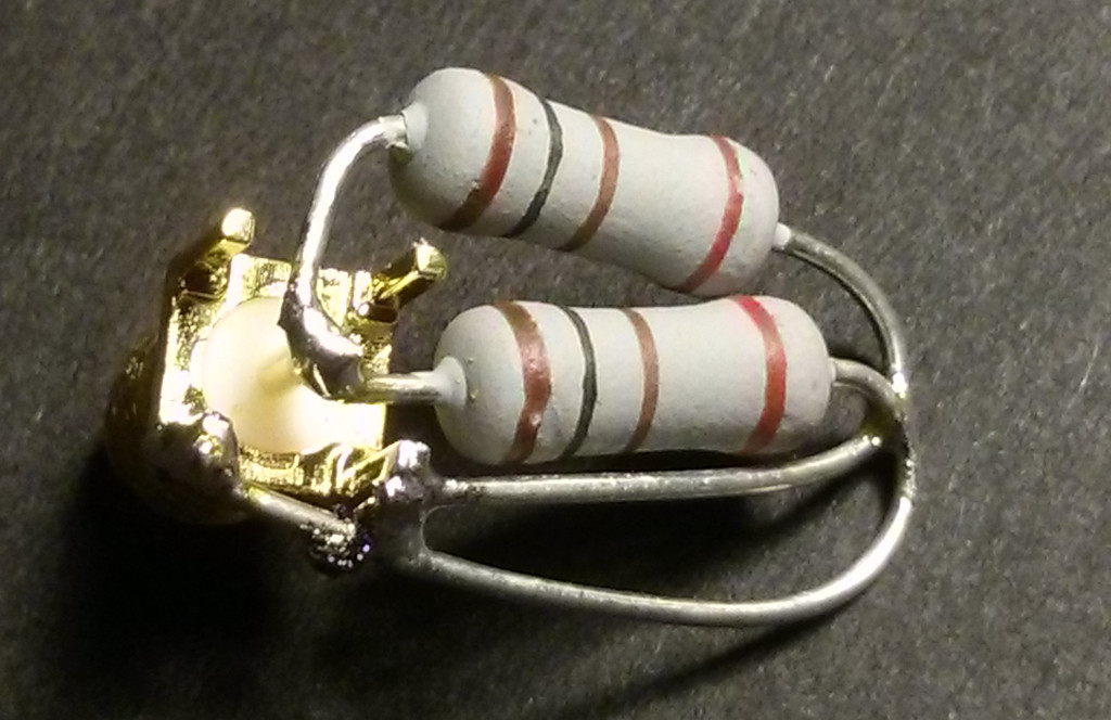
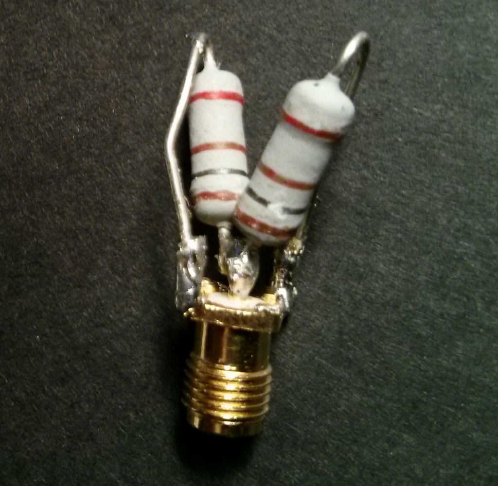
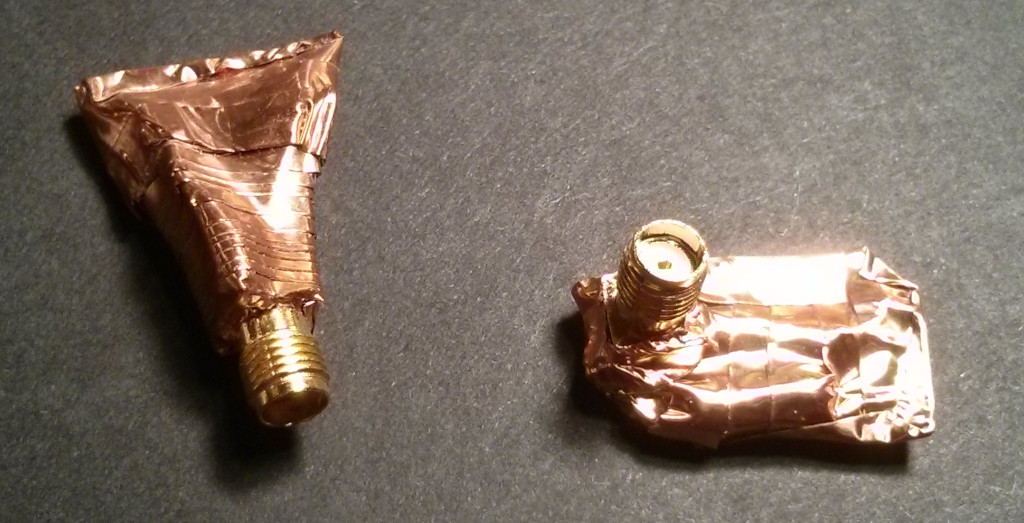
These 4-watt dummy loads are overkill (since I can set the UV-5RA to 1 watt during testing), but I wanted to ensure that it could handle the max power (and heat) in case I forgot to set the power level beforehand, and they only seem to get warm to the touch during sporadic packet testing which allows them time to cool. I don't have a field strength meter, but I tested transmissions to a high-gain 2-meter antenna, and after a few hundred meters line-of-sight, the signal was inaudible and had reached the noise floor. But at 3 feet away, they can hear each other well, and I also place the antenna for the RTL2832U running GQRX spaced equidistantly between them so that I can see the spectrogram and adjust them to match each other.
More Ideas and Hindsight
- The Pi 3 also works with this interface but requires the same UART settings as the Pi Zero (see the section above for more information).
- When I first designed the schematic, I didn't realize that solar, rechargeable lithium 5V USB battery packs and variable switching DC-to-DC boost converters↗ had gotten so inexpensive, so in my newer TrillSat project, I did not use a battery eliminator or 12 volt battery and instead used 5 volts from a USB powerbank for a Raspberry Pi Zero W and added a 5 Amp LM2587S-ADJ boost-converter to produce the 7.4 volts needed for the radio, although it may add a little bit of switching noise that might need additional filtering. For more quiet operation, also used sets of 3.6 volt Panasonic NCR18650B Lithium-ion cells in series to obtain nominal 7.2 volts, which worked well. The radio does not require exactly 7.4 volts as marked on the label and will operate over a varying range. I don't know exactly what this range is, but I assume this is the nominal value of the Baofeng rectangular Lithium-ion pack (probably 2 cells in series, as well). On my UV-5RA after a full battery charge, I measured 8.28 volts at the Baofeng battery, so the radio must be designed to operate as the battery discharges and the voltage lowers. In my testing, it operates under 7.4 volts, but I'm not sure where the exact cutoff is.
- Being remotely-operated and easy to self-contain it reminded me more of a mini communication satellite than a fixed station and antenna, which led me to later building TrillSat. And it is so small, lightweight, and inexpensive, that, with some additional sensors, it could be useful for amateur radio High Altitude Ballooning projects, which could be thought of as slow-moving near-space satellites. WiFi would go out of range fairly quickly, but the UV-5RA transmitter could send out a beacon that could be received from far away, since line-of-sight at high-altitudes would be very distant. But for something like this, in the US, both FCC and FAA regulations would come into play, and it would need some modifications.
- I just used a traditional electromechanical relay for the power switching in my schematic as an example, but when I actually built TrillSat, which incorporates such a power-control system, I replaced the relay with a solid-state, P-channel FQP27P06 logic-level MOSFET which eliminates mechanical failures and switching noise. Relays, though, still perform better in many situations, and are definitely not obsolete. In TrillSat, for example, even though I incorporated many high-current MOSFETs, I still used DPDT relays for low-power situations (bistable or "latching") and low-contact resistance (to ensure the Lithium-ion charger saw the precise voltage).
- During this project, I tried to figure out ways of getting the UV-5RA to operate on two different frequencies in a near simultaneous manner, as it is a dual-band transceiver with a dual watch mode. I tried two approaches (using dual-watch mode and using clone-mode flash), but only the latter seemed to work well for me:
- Dual-watch mode can somewhat mimic a dual VFO. The radio can be configured to receive the signals from two different frequencies in a time-sharing manner (and also auto-set to transmit out on the last frequency received), but since this is an open-loop control system that will get out of sync with the Raspberry Pi, the Pi can't really be certain which frequency the radio is set to transmit out on. However, the transmit channel can be locked to A or B, and it could be configured to receive 2 known frequencies and transmit out on 1. I guess it could operate as a packet station while also being set up as a time-shift audio recorder for scheduled voice nets on the other frequency, however they would come into time conflicts with each other, causing loss of data. Or perhaps it could receive and log data transmissions on the other frequency as long as they were short bursts that were periodic. The split cross-band mode set in Chirp is interesting, too, and but it would have the same time-sharing impairment as mentioned above.
- Clone-mode flash, however, can do something interesting. The primary problem is that the UV-5RA only has a single VFO. It wasn't until I built TrillSat that I found a way for the single VFO to act like two, which allows the software to instruct the radio to switch between two frequencies (especially useful for creating both a packet and APRS station, which use different frequencies). Chirp can't control this radio live but only in clone mode, where it can update the settings. Luckily, the "work mode" settings include the VFO frequency. Chirp can program the entire flash memory to change the VFO frequency, and the radio will re-boot on the new frequency. But this takes a while, and Chirp is a GUI-based client, so this is difficult to achieve programmatically and would require an X-windows installation (where I run headless servers without the GUI). A neat command-line version called Chirpc does not require the GUI, but it also takes a while (as it writes the entire flash), and it did not have an option to control the VFO frequency, like Chirp did. So I couldn't use Chirp or Chirpc and instead, I identified the memory location of the frequency and directly wrote a 16-byte chunk of flash memory that held the 8-byte memory location of the VFO A frequency, which was much faster than a full clone (a few seconds) and doesn't cause needless writes to the other memory locations. This allows the clone-mode radio to operate as if it is controlled in real-time. So now I can switch to APRS, send out a beacon, and then switch back and resume packet sessions that are still in progress, since it is so fast and AX.25 tolerates such delays which can be extended in real-time using tools such as kissparms and axctl. Please see the TrillSat project for more information on this technique.
- If you don't have a free hardware UART to program the UV-5RA flash, the Python pigpio↗ library (using the gpio bb_serial and wave functions) and pigpiod daemon can create a virtual UART at 9600 baud that will successfully allow programming of the radio, even on devices as slow as a Raspberry Pi Zero, which I successfully did on my TrillSat project. This is nice if you have a Pi Zero without the wifi connection and are using the UART as your only serial terminal or are using the UART for other devices.
- In TrillSat, I added an ESP8266↗ as a secure control link over WiFi which allows me to power down the Raspberry Pi completely and not lose the link. It's an extremely useful and inexpensive chip, and if someone creates an AX.25 stack for the ESP8266, it could be a remotely-operated station that would be even cheaper and use less power than a Pi Zero. Less-complex digital modes would be even easier to program.
- I used a USB audio device, since it was all I had. But USB audio is not ideal, since it competes with USB bandwidth, which is shared internally by the Ethernet adapter. There are now audio cards available for the Pi that connect directly to the I2S (Integrated Interchip Sound) port, eliminating any USB audio issues. I bought my UCA202 before such cards existed, but the USB audio cards still seem to be the cheapest at the time of this writing, especially cards like the SYBA SD-CM-UAUD that I used for TrillSat.
- I could have used the headphone jack of the UCA202 instead of the line out and used the built-in volume control instead of using a potentiometer. I did this in my later TrillSat project when I switched to the SYBA SD-CM-UAUD. But for this project, I wanted to use the headphone jack for headphones so that I could monitor the sounds. Also, ALSA softvol↗ would just lower the software level volume, not the line level, so the noise level will be higher.
Hardware
- Raspberry Pi 2
- Behringer UCA202
- Baofeng UV-5RA
- 1/4 watt 10 K ohm resistor
- 1/4 watt 100 ohm resistor
- 50 K ohm potentiometer
- 10 uF capacitor
- Two female RCA phono jacks (I cut up an old Y cable)
- 4-conductor telephone wire
- RJ-11 plug and jack (I used a crimper tool)
- 2-pin Kenwood-style TRS connector (I cut the one from the included headset)
Optional 3 amp Power Control:
- External 12 V, 3 amp power source
- 12v Battery Eliminator adapter that works with UV-5RA
- 16 gauge wire
- 3 amp fuse
- 1/4 watt 1 K ohm resistor
- 2N2222 NPN transistor
- 3 amp SPST N.O. relay with a 5 volt, low current coil
- 1N4148 diode
Optional SDR for monitoring:
- RTL2832U-based USB Stick (for spectrum analyzer)
Optional Dummy Load for testing:
- Two 50 ohm, 100-watt, non-wirewound resistors
- Female SMA PCB Jack
- 8mm Kapton tape (for high-temp interior insulation)
- 5mm copper foil tape (for outer ground shield)
Software
The version of Arch Linux↗ below is for the ARM architecture. The software packages can be found in Arch AUR↗. However, at the time of this writing, I had to download and compile the latest daily build of Chirp to get it to work.
- Arch Linux ARM↗
- soundmodem↗
- Linux AX.25 software
- ax25-apps
- ax25-tools
- libax25
- chirp↗
- optional direwolf-git (if replacing Soundmodem with Dire Wolf)
- optional qsstv (if using SSTV)
- optional GQRX↗ (for spectrum analyzer--run on a fast PC)
Conclusion
This interface project was exciting and reminded me of my earlier BBS days using my Commodore 64 modem. Now I am just trying to combine new things that I've learned about radio with a very old radio history of FM and packet, while also adding modern concepts like the Raspberry Pi series, Baofeng Handy Talkie, SDR, and Arch Linux. In building a second packet radio interface for my TrillSat craft, I improved upon this design in some respects. However, even after 11 years, I continue to use this interface for my ground station to communicate with TRILLSAT-1. I 3D-printed a tray to hold the components (which I call TRILLSAT-G), added an ESP8266 for XMPP control via smartphone, added a USB powerbank, and added a 50-ohm dummy load for testing:
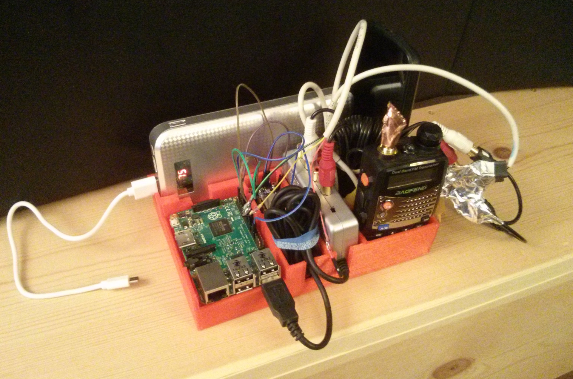
I finally put some of the concepts from the ARRL Ham Radio License Manual (Technician Class), ARRL General Class License Manual, ARRL Handbook_, and ARRL Operating Manual into actual use, and now I understand why my instructor emphasized certain concepts that I thought were rather obscure. The Technician manual is especially becoming more and more relevant and concise to me as time goes by.
I made a rare journey through the 4 mountain passes of impedance, reactance, deviation, and propagation and returned safely to my digital armchair in the valley, my stable fixed point↗ by the juniper twig fire.
Comments